Verify the A (Main) and B (Delayed) trigger systems.
Equipment required Prerequisites
<4 GHz models: One precision 50 Ω coaxial
cable (Item 4)
<4 GHz models: One BNC to Minigrabber
adapter (item 18)
≥4 GHz models: One SMA cable (item 21)
≥4 GHz models: One adapter (item 19)
None
1. Initialize the instrument: Push the front-panel Default Setup button.
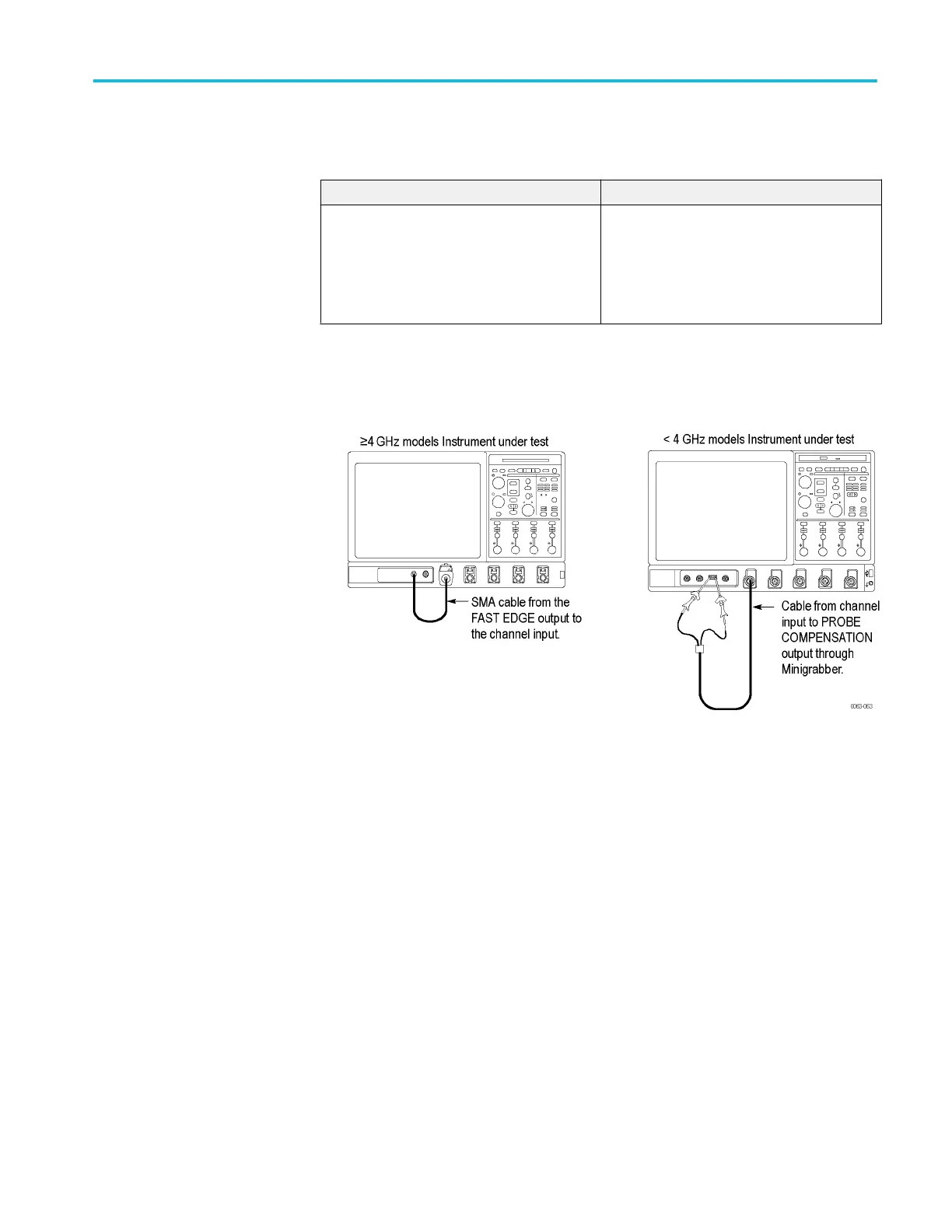
2. Hook up the signal source: Connect the probe compensation or fast edge
output to the Ch 1 input as shown in the following figure.
Figure 5: Setup for trigger test
3. Set up the instrument: Push the front-panel Autoset button.
4. Set the Vertical Scale to 200 mV /div (≤20 GHz models) or 120 mV/div
(>20 GHz models).
5. Verify that the main trigger system operates: Confirm that the following
statements are true.
■
The trigger level readout for the A (main) trigger system changes with
the trigger-Level knob.
■
The trigger-Level knob can trigger and untrigger the square-wave signal
as you rotate the knob. (Leave the signal untriggered).
■
Pushing the front-panel trigger Level knob sets the trigger level to the
50% amplitude point of the signal and triggers the signal that you just left
untriggered. (Leave the signal triggered.)
6. Verify that the delayed trigger system operates:
a. Set up the delayed trigger:
Pull down the Trig menu and select A – B Trigger Sequence. . . . This
displays the A →B Sequence tab of the trigger setup control window.
Performance verification (MSO/DPO70000C, MSO/DPO70000DX, and DPO7000C series)
MSO70000C/DX, DPO70000C/DX, DPO7000C, MSO5000/B, DPO5000/B Series 109
 Loading...


