Model 7700 Multiplexer Module Instructions for use with DAQ6510
16 077144300 / April 2018
To verify DC voltage accuracy:
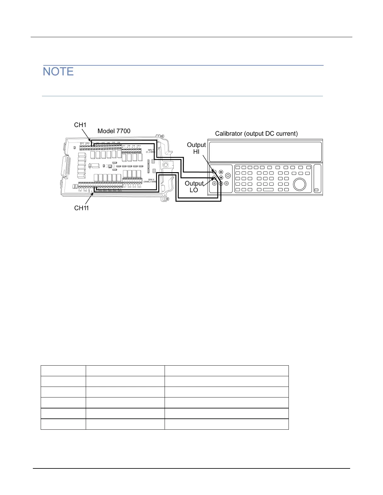
1. Connect the CH1 H and L INPUT terminals to the DC voltage calibrator as shown in the next figure.
Use shielded, low-thermal connections when testing the 100 mV and 1 V ranges to avoid errors
caused by noise or thermal effects. Connect the shield to the output LO terminal of the calibrator.
Figure 6: 7700_ConnectionsDCVVerify
2. Install the module in Slot 1 of the DAQ6510.
3. Turn on the power.
4. Allow the instrument to warm up for one hour.
5. Make sure that the front-panel TERMINALS switch is set to REAR.
6. On the front panel of the instrument, select the FUNCTION key and then select DC Voltage.
7. On the Home screen, swipe to the CHANNEL swipe screen.
8. Close channel 101.
9. Set the range to 100 mV.
10. Set the calibrator output to 0.00000 mV DC.
11. Allow the reading to settle.
12. Swipe to the Settings screen.
13. Enable Rel.
14. For the calibrator, source positive, negative, and full-scale voltages, see the ranges listed in the table
below. For each voltage setting, make sure that the reading is within stated limits.
15. Return to the CHANNEL swipe screen, and open Channel 1.
Range Applied DC voltage Reading limits (1 year, 18 °C to 28 °C)
100 mV 100.0000 mV 99.9935 to 100.0065 mV
1 V 1.000000 V 0.999969 to 1.000031 V
10 V 10.00000 V 9.99970 to 10.00030 V
100 V 100.0000 V 99.9955 to 100.0045 V
1000 V 300.000 V 299.983 V to 300.017 V
 Loading...