Model 7700 Multiplexer Module Instructions for use with DAQ6510
18 077144300 / April 2018
ACV range Applied AC voltage
1 kHz reading limits
(1 year, 18 °C to 28 °C)
50 kHz reading limits
(1 year, 18 °C to 28 °C)
100 mV 100.0000 mV 99.910 to 100.090 mV 99.830 to 100.170 mV
1 V 1.000000 V 0.99910 to 1.00090 V 0.99830 to 1.00170 V
10 V 10.00000 V 9.9910 to 10.0090 V 9.98300 to 10.0170 V
100 V 100.0000 V 99.910 to 100.090 V 99.830 to 100.170 V
750 V 300.000 V* 299.60 to 300.40 V 299.27 to 300.73 V
* If the 5725A amplifier is not available, change the 300 V @ 50 kHz step to 220 V @ 50 kHz. Reading limits
for 220 V @ 50 kHz = 219.36 V to 220.64 V.
Verifying resistance
Check resistance by connecting accurate resistance values to the module and verifying that its resistance
readings are within the specified limits.
Do not apply more than 300 VDC between the module INPUT or SENSE H and L terminal or
between any adjacent channels. Failure to observe this precaution can cause instrument
damage.
To verify resistance accuracy:
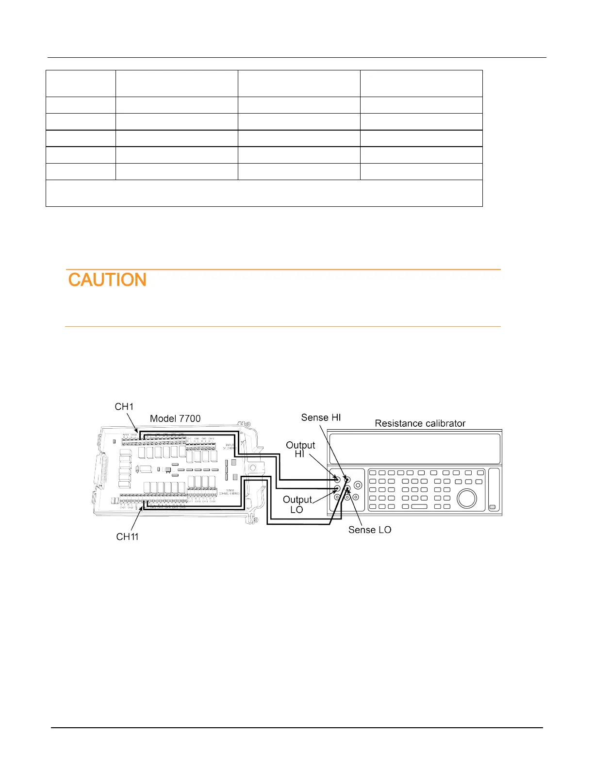
1. Using shielded Teflon or equivalent cables in a 4-wire configuration, connect the 7700 CH1 H and L INPUT
terminals and CH11 H and L SENSE terminals to the calibrator as shown in the next figure.
Figure 8: Connections for resistance verification
2. Install the module in Slot 1 of the DAQ6510.
3. Turn on the power.
4. Allow the instrument to warm up for one hour.
5. Make sure that the front-panel TERMINALS switch is set to REAR.
6. Set the calibrator for 4-wire resistance with external sense on.
7. On the front panel of the instrument, select the FUNCTION key and then select 4W Resistance.
8. On the Home screen, swipe to the CHANNEL swipe screen.
9. Set the range to 100 Ω range.
10. Swipe to the Settings screen.
11. Enable the Filter.
 Loading...