Model 7700 Multiplexer Module Instructions for use with DAQ6510
077144300 / April 2018 19
12. For the 100 Ω range, select the MENU key, select Channel Settings, and set Offset Compensation to On.
13. Recalculate reading limits based on actual calibrator resistance values.
14. Source the nominal full-scale resistance values for the 1 Ω to 100 MΩ ranges listed in the table below.
Verify that the readings are within calculated limits.
Ω Range
Nominal
resistance
Nominal reading limits
(1 year, 18°C to 28°C)
Recalculated limits**
1 Ω* 1 Ω 0.999715 mΩ to 1.000285 Ω __________ to __________ Ω
10 Ω 10 Ω 9.99895 mΩ to 10.00105 Ω __________ to __________ Ω
100 Ω 100 Ω 99.9895 Ω to 100.0105 Ω __________ to __________ Ω
1 kΩ 1 kΩ 0.999929 Ω to 1.000081 kΩ __________ to __________ kΩ
10 kΩ 10 kΩ 9.99929 Ω to 10.00081 kΩ __________ to __________ kΩ
100 kΩ 100 kΩ 99.9905 Ω to 100.0095 kΩ __________ to __________ kΩ
1 MΩ 1 MΩ 0.999894 Ω to 1.000106 MΩ __________ to __________ MΩ
10 MΩ 10 MΩ 9.99590 Ω to 10.00410 MΩ __________ to __________ MΩ
100 MΩ 100 MΩ 99.7970 Ω to 100.2030 MΩ __________ to __________ MΩ
* Enable offset compensation for the 1 Ω range.
** Calculate limits based on actual calibration resistance values and DAQ6510 one-year
resistance accuracy specifications. See Calculating resistance reading limits (on page 13
) for
more information.
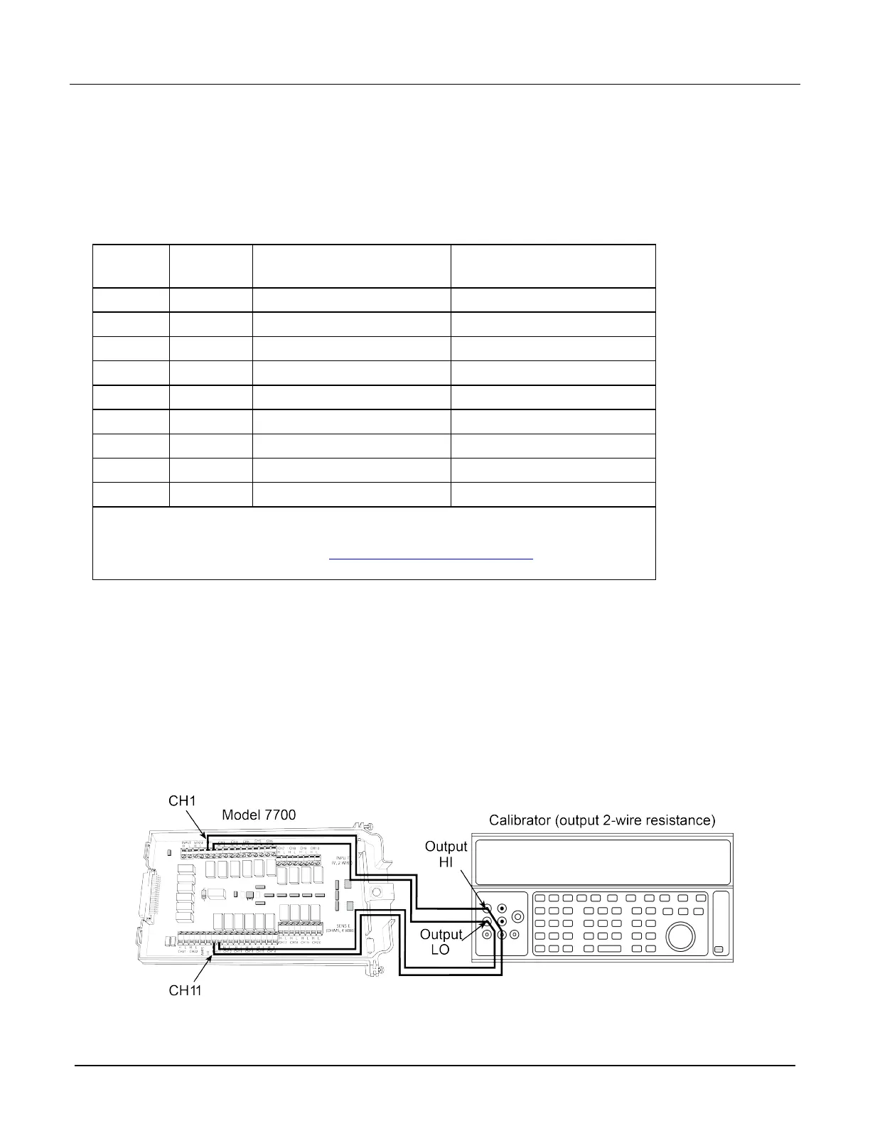
1. Connect the CH1 and CH11 terminals of the module to the calibrator as shown in the next figure.
2. Disable external sense on the calibrator.
3. Set the range of the DAQ6510 to 100 MΩ range.
4. Source a nominal 100 MΩ resistance value. Verify that the reading is within calculated limits for the 100 MΩ
range.
5. Return to the CHANNEL swipe screen, and open Channel 1.
Figure 9: Connections for resistance verification (100 MΩ range)
 Loading...