Home
Tektronix
Test Equipment
MSO5000 Series
Tektronix MSO5000 Series User Manual
4
of 1
of 1 rating
212 pages
Give review
Manual
Specs
To Next Page
To Next Page
To Previous Page
To Previous Page
Loading...
Pinpoint
T
rigge
rs
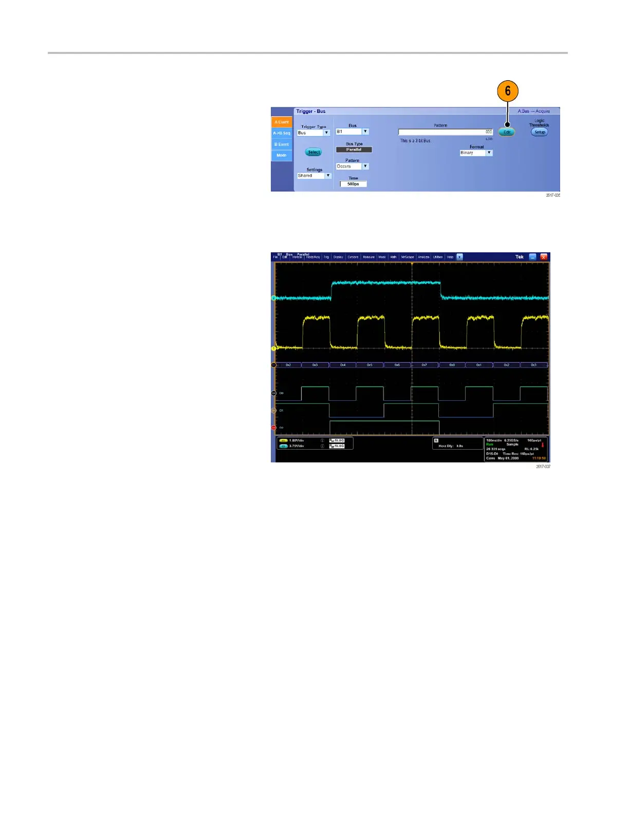
5.
Click
the
Edit
button
to
set
the
pattern
and
format
that
you
want
to
trigger
on.
6.
Set
the
pattern
to
trigger
on
using
the
keypad.
7.
Analyze
your
waveforms.
82
MSO70000/C,
DPO/DSA70000B/C,
DPO7000,
and
MSO/DP
O5000
Series
U
ser
M
anual
101
103
Table of Contents
Table of Contents
7
General Safety Summary
11
Compliance Information
13
EMC Compliance
13
Safety Compliance
15
Environmental Considerations
17
Preface
18
Key Features
18
Documentation
20
Conventions Used in this Manual
20
Install Your Instrument
21
Standard Accessories
21
Operating Requirements
22
Preventing ESD
25
Powering on the Instrument
25
Powering off the Instrument
27
Removing the Power
27
Securing the Oscilloscope
28
Connecting to a Network
29
Adding a Second Monitor
30
Operating System Restore
35
Installing the MSO5000 and DPO5000 Hard Drive
35
Getting Acquainted with Your Instrument
36
Front Panel
36
Side and Rear Panels
37
Interface and Display
41
Control Panel
43
Accessing Online Help
45
Accessing Menus and Control Windows
46
Inspect Your Instrument
48
Verify Internal Diagnostics Pass
48
Acquisition
49
Signal Path Compensation
49
Setting up Analog Signal Input
51
Using Default Setup
53
Using Autoset
54
Probe Compensation, Calibration, and Deskew
55
Acquisition Concepts
55
How the Acquisition Modes Work
58
Changing the Acquisition Mode
59
Starting and Stopping an Acquisition
60
Selecting the Horizontal Mode
60
Using Fastacq
63
Using DSP Enhanced Bandwidth
65
Using Roll Mode
67
Setting up Digital Signal Input
68
Setting up Digital Channels
68
Setting up a Bus
70
When and Why to Turn on Magnivu
76
Using Magnivu
76
Viewing Analog Characteristics of Digital Waveforms
77
Using Fastframe Mode
79
Using Fastframe Frame Finder
81
Using Teklink and Multiscope Trigger
83
Pinpoint Triggers
87
Triggering Concepts
87
Choosing a Trigger Type
89
Trigger Selections
91
Checking Trigger Status
93
Using a (Main) and B (Delayed) Triggers
94
Triggering with B-Event Scan
97
Triggering on a Parallel Bus
100
Triggering on a Serial Bus
103
Sending E-Mail on Trigger
105
Setting up E-Mail on Event
106
Using Horizontal Delay
107
Display a Waveform
109
Setting the Display Style
109
Setting the Display Persistence
110
Setting the Display Format
111
Selecting the Waveform Interpolation
112
Adding Screen Text
113
Setting the Graticule Style
114
Setting the Trigger Level Marker
115
Displaying the Date and Time
115
Using the Color Palettes
116
Setting Reference Waveform Colors
117
Setting Math Waveform Colors
117
Using Multiview Zoom
117
Zooming in Multiple Areas
119
Lock and Scroll Zoomed Waveforms
121
Hide Waveforms in the Zoomed Window
122
Using Wave Inspector to Manage Long Record Length Waveforms
123
Searching and Marking Waveforms
125
Analyzing Waveforms
133
Taking Automatic Measurements
133
Automated Measurement Selections
135
Customizing an Automatic Measurement
138
Taking Cursor Measurements
141
Setting up a Histogram
143
Using Math Waveforms
145
Using Spectral Analysis
148
Using Mask Testing
151
Using Limit Testing
155
Myscope
157
Creating a New Myscope Control Window
157
Using Myscope Control Windows
161
Saving and Recalling Information
163
Saving Screen Captures
163
Saving Waveforms
164
Recalling Waveforms
166
Saving Digital Waveforms
167
Saving Instrument Setups
168
Recalling Instrument Setups
169
Saving Measurements
170
Saving User Masks
171
Saving Histogram Data
172
Saving Timestamps
173
Copying Your Results to the Clipboard
174
Printing a Hard Copy
175
Run Application Software
177
Application Examples
179
Capturing Intermittent Anomalies
179
Using the Extended Desktop and Openchoice Architecture for Efficient Documentation
183
Triggering on Buses
185
Triggering on a Video Signal
186
Correlating Data between a Tektronix Oscilloscope and Logic Analyzer
188
Appendix
189
Cleaning
189
Appendix
190
Obtaining the Latest Oscilloscope Application and Version Releases
190
Appendix
191
TPP0500 and TPP1000 500 Mhz and 1 Ghz 10X Passive Probes Instructions
191
Operating Information
191
Connecting the Probe to the Oscilloscope
191
Compensating the Probe
192
Standard Accessories
192
Optional Accessories
194
Replacing the Probe Tip
194
Specifications
194
Performance Graphs
195
Safety Summary
196
Appendix
198
P6616 General-Purpose Logic Probe Instructions
198
Product Description
198
Connecting the Probe to the Oscilloscope
199
Connecting the Probe to Your Circuit
200
Functional Check
200
Typical Application
201
Accessories
201
Specifications
202
Safety Summary
203
Safety Terms and Symbols in this Manual
203
Contacting Tektronix
204
Warranty Information
204
4
Based on 1 rating
Ask a question
Give review
Questions and Answers:
Need help?
Do you have a question about the Tektronix MSO5000 Series and is the answer not in the manual?
Ask a question
Tektronix MSO5000 Series Specifications
General
Brand
Tektronix
Model
MSO5000 Series
Category
Test Equipment
Language
English
Related product manuals
Tektronix MSO5054
213 pages
Tektronix MSO5054B
222 pages
Tektronix MSO5034B
222 pages
Tektronix MSO54
50 pages
Tektronix MSO58
1026 pages
Tektronix MSO56
1026 pages
Tektronix MSO54B
143 pages
Tektronix MSO56B
143 pages
Tektronix MSO5204
213 pages
Tektronix MSO5104
213 pages
Tektronix MSO5204B
222 pages
Tektronix MSO5104B
222 pages