THM500 Series Performance Verification
Handheld and Benchtop Instruments Basic Service
21
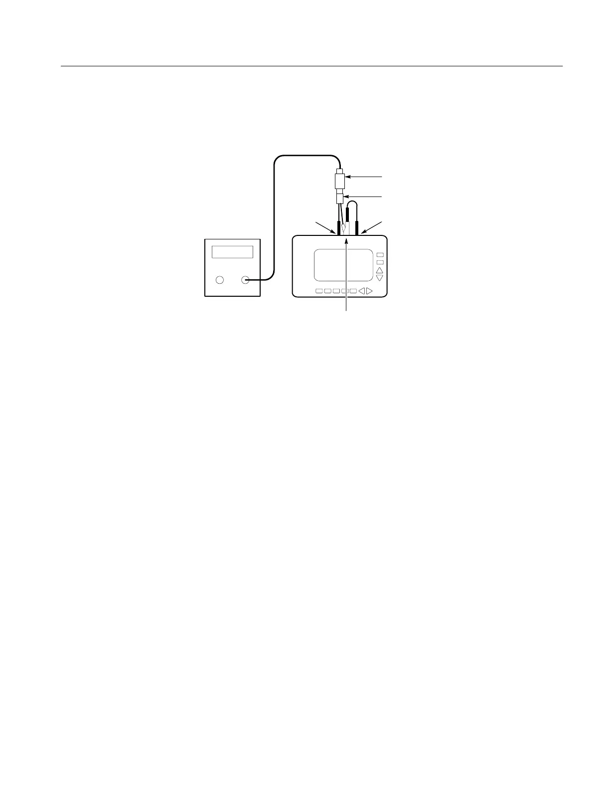
2. Connect the THM500 series instrument CH 1 input to the COM input using
a patch cord as shown in Figure 9.
THM5xx
CH 1DMM
COM
50 termination
50 cable
Leveled Sine
Wave
generator
BNC to dual banana cable
Figure 9: Crosstalk Between DMM And Scope Test Setup
3. Set the leveled sine wave generator for a 2.5 V
p-p
signal at 5 MHz.
4. On the THM500 series instrument, press the POSITION/SCALE button
until the readout shows SCALE in the lower-right corner. Use the
Y
and
B
buttons to set the vertical scale to 50 mV/div and the
A
and
"
buttons to set
the time base to 2000 ms/div.
5. Use the THM500 series instrument menus to set the sampling mode to
SPIKE DETECT; then remove the menus from the display.
6. Verify that the peak-to-peak amplitude is less than 0.5 divisions (25 mV
p-p
).
The following check assesses the crosstalk between oscilloscope channels. If
your instrument has only one channel (THM550), do not perform this test.
1. Connect the leveled sine wave generator output to the THM500 series
instrument CH 1 and COM inputs. Use a 50 W termination as shown in
Figure 10. Assure that the ground connection for each adapter connects to
the common (or ground) connector of its associated instrument.
2. Connect the THM500 series instrument CH 2 input to the COM input using
a patch cord as shown in Figure 10.
Crosstalk Between
Oscilloscope Channels
 Loading...


