THM500 Series Performance Verification
22
Handheld and Benchtop Instruments Basic Service
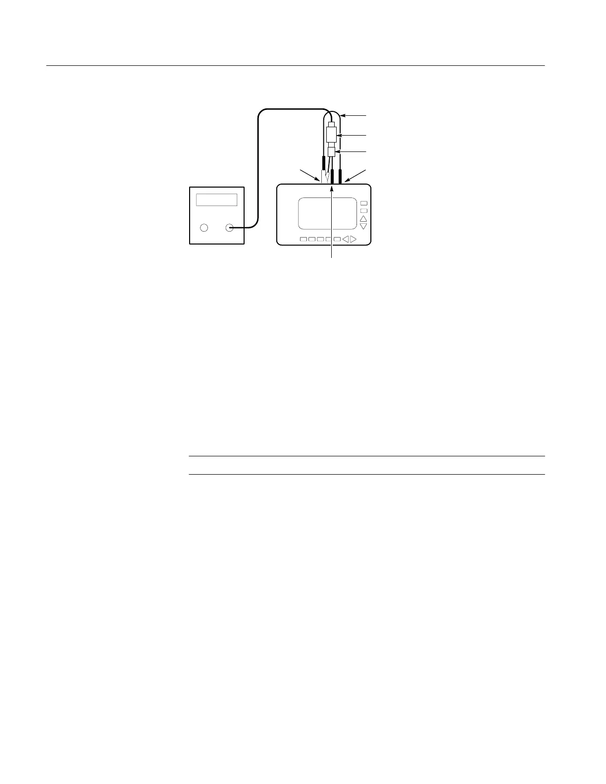
THM5xx
CH 2COM
CH 1
50 termination
50 cable Patch cord
Leveled Sine
Wave
generator
BNC to dual banana cable
Figure 10: Crosstalk Between Scope Channels Test Setup
3. On the THM500 series instrument, press the POSITION/SCALE button
until the readout shows SCALE in the lower-right corner. Use the
Y
and
B
buttons to set the CH 1 vertical scale to 500 mV/div and the
A
and
"
buttons to set the time base to 200 ms/div.
4. Use the THM500 series instrument menus to set the sampling mode to
SPIKE DETECT; then remove the menus from the display.
5. Adjust the leveled sine wave generator to display five divisions peak-to-peak
at 5 MHz.
NOTE. The 5 MHz waveform is aliased and appears untriggered.
6. Press the THM500 series instrument WAVEFORM ON/OFF button to turn
the CH 1 waveform display off.
7. Press the THM500 series instrument SELECT button to select CH 2. Press
the WAVEFORM ON/OFF button to turn on channel 2. Press the POSI-
TION/SCALE button to show SCALE; then use the
Y
and
B
buttons to set
the vertical scale to 50 mV/div.
8. Verify that the peak-to-peak signal displayed on the THM500 series
instrument channel 2 is less than 0.5
divisions (25 mV
p-p
).
9. Disconnect the test setup.
 Loading...


