Do you have a question about the Tektronix TBS1022 and is the answer not in the manual?
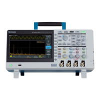
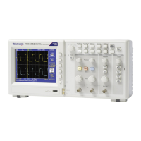
The TBS1000, TBS1000B/TBS1000B-EDU, TDS1000B/TDS2000B, TDS1000C-EDU/TDS2000C, and TPS2000B Series Digital Storage Oscilloscopes are sophisticated instruments designed for capturing, storing, and analyzing electrical signals. These devices are essential tools for engineers, technicians, and educators who require precise measurement and visualization of waveforms in various applications, from circuit debugging to educational demonstrations. The core function of these oscilloscopes is to convert analog electrical signals into digital data, which can then be displayed on a screen, stored for later analysis, or exported to other devices.
At its heart, the oscilloscope functions as a signal visualization and measurement tool. It acquires analog signals through its input channels, digitizes them using an analog-to-digital converter (ADC), and then processes this digital data to display waveforms on its screen. This process allows users to observe the shape, amplitude, frequency, and other characteristics of electrical signals over time. The instrument's acquisition memory, comprising SDRAM and LPDDR SDRAM, plays a crucial role in temporarily holding these digitized waveforms for processing and display. This memory is volatile, meaning data is lost when the instrument is powered off, ensuring that transient user data does not persist.
Beyond basic waveform display, these oscilloscopes offer a range of advanced functions. They can perform various automatic measurements, such as peak-to-peak voltage, frequency, and rise time, simplifying the analysis process. Users can also save instrument setups, which include all current measurement parameters and display configurations, to nonvolatile flash memory. This feature is particularly useful for recurring tests or for sharing specific test conditions among users. Reference waveforms, which are captured signals saved for comparison, can also be stored in nonvolatile memory, allowing users to compare live signals against known good or bad waveforms. Hard copy image files, essentially screenshots of the oscilloscope display, can be saved for documentation purposes, facilitating report generation and record-keeping. Calibration constants, essential for maintaining the accuracy of the instrument's measurements, are also stored in nonvolatile flash memory.
The oscilloscopes incorporate a real-time clock, which holds date/time data. This is an important feature for timestamping saved data and for general record-keeping, although it does not store user data or settings directly. The USB processor, with its dedicated EEPROM and SRAM, manages USB communication, enabling data transfer and remote control capabilities.
The oscilloscopes are designed with user-friendliness in mind, offering multiple ways to interact with the instrument and manage data. The front panel features a variety of buttons and controls, including a DEFAULT SETUP button to quickly recall factory settings, and a SAVE/RECALL button for managing saved setups and waveforms. Option buttons, often referred to as side bezel buttons, provide context-sensitive controls for various functions, making navigation intuitive.
Data input methods are diverse, catering to different user needs. Firmware operations allow the instrument to perform internal tasks and process data. User input, through the front panel controls, enables direct interaction and configuration. Factory configurations are pre-set parameters that ensure the instrument operates correctly out of the box. USB disk upgrades facilitate firmware updates and software enhancements.
For data export, the instruments are equipped with USB host ports, which support removable USB flash drives. This allows users to save reference waveforms, screen images, and instrument setups directly to an external drive. The USB device port, located on the rear panel, enables remote control and data transfer to a PC via USBTMC (USB Test and Measurement Class), making it easy to integrate the oscilloscope into automated test systems or to perform data analysis on a computer. TPS oscilloscopes also feature a compact flash card slot on the front panel for user storage of reference waveforms, screen images, and instrument setups, offering an alternative portable storage solution.
The ability to save and recall instrument setups is a significant usage feature, allowing users to quickly switch between different test configurations without manually re-entering all parameters. Similarly, saving reference waveforms enables efficient comparison and troubleshooting. The hard copy image file export function is invaluable for creating documentation, presentations, or educational materials.
Maintenance, particularly concerning data security and declassification, is a critical aspect of these instruments. The manual provides detailed procedures for clearing and sanitizing memory devices, ensuring that sensitive data can be eradicated when the instrument is moved from a secure environment or disposed of.
For volatile memory devices (SDRAM, SRAM, LPDDR SDRAM), clearing and sanitizing simply involves removing power from the instrument for at least 20 seconds. This ensures that all temporary user data and settings are lost. The real-time clock, which is battery-backed, requires the battery to be removed from the board to clear its date/time data.
Nonvolatile memory devices, such as the main flash memory and Nand flash, require more elaborate procedures for clearing and sanitizing. The "Clear the flash memory" procedure involves a series of steps to overwrite all user-modifiable data and settings with default or null values. This includes recalling default setups, overwriting all saved setups and reference waveforms with null data, and overwriting hard copy image files with an image that contains no useful information. This process effectively erases user data without affecting the instrument's core firmware or calibration constants. For the EEPROM, which stores program memory for the USB processor and does not contain user data, no clearing or sanitizing is necessary, as doing so would disable instrument functionality.
In cases where an instrument is non-functional, specific procedures are outlined for declassification. This typically involves removing key components that store data, such as the Acquisition board, compact flash card (for TPS models), or USB flash drive (for TBS and TDS models), and returning them to Tektronix for repair or proper disposal according to internal company policies. This ensures that any potentially sensitive data stored on these components is handled securely. The manual also notes that replacement of any missing hardware will be charged, emphasizing the importance of following proper procedures for component removal and return.
The declassification and security instructions are designed to meet stringent requirements, such as those specified in NISPOM, DOD 5220.22–M, Chapter 8, and the ISFO Process Manual for Certification & Accreditation of Classified Systems under NISPOM. This commitment to security ensures that these oscilloscopes can be used in environments with high data protection demands.
| Bandwidth | 25 MHz |
|---|---|
| Channels | 2 |
| Sample Rate | 1 GS/s |
| Record Length | 2.5 kpoints |
| Vertical Resolution | 8 bits |
| Timebase Range | 5 ns/div to 50 s/div |
| Display Type | TFT LCD |
| Connectivity | USB 2.0 |
| Display | 7 inch TFT |
| Weight | 2.2 kg |
| Trigger Modes | Edge, Pulse, Video |
| Input Impedance | 1 MΩ |
| Power Supply | 100 to 240 V ±10%, 45 Hz to 66 Hz |