Removal and Replacement
TDS 340A, TDS 360 & TDS 380 Technical Reference
6–17
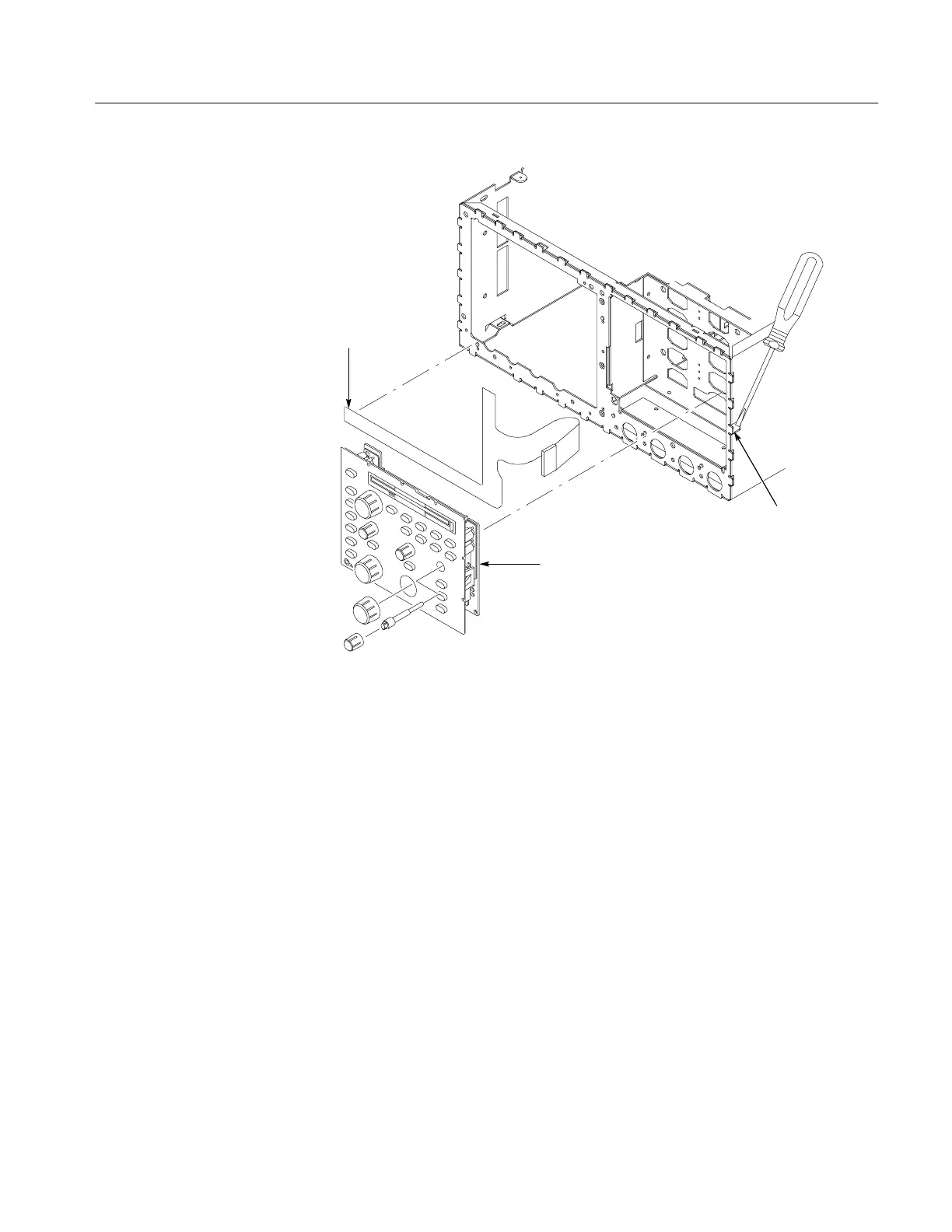
Menu flex
circuit
Front panel
assembly
Press latch
to release
Figure 6–9: Front panel assembly and menu flex circuit removal
7. If you are removing the menu flex circuit, pull the circuit away from the
front of the main chassis.
8. If you do not need to perform component-level service on the front-panel
assembly, skip to step 15 for reinstallation instructions.
9. Remove the front-panel control knobs from the front-panel assembly using
the method described in Front-Panel Knobs and Shafts on page 6–10.
10. Release the three snap locks at the edge of the circuit board, then tilt the
board away from the assembly until it unplugs from J405. See Figure 6–10.
11. Slide the circuit board out from the retainers found at the edge opposite the
snap locks and lift it away from the rest of the assembly.
12. Hand disassemble the front-panel-assembly components using Figure 6–10
as a guide. Reverse the procedure to reassemble.
 Loading...


