Operating Information
TDS 340A, TDS 360 & TDS 380 Technical Reference
2–5
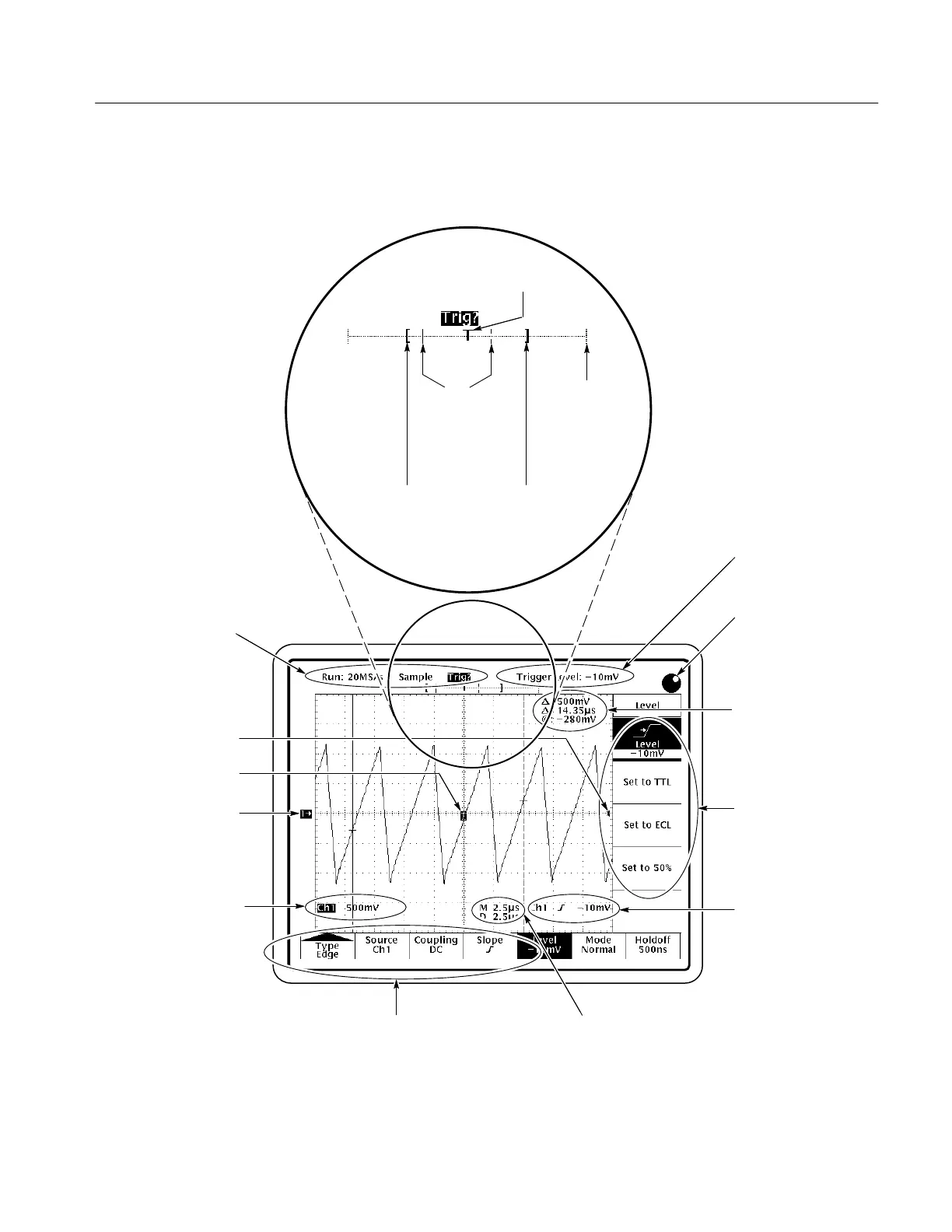
Display Map
The Status Readouts show
trigger status and acquisition
status (mode and sampling rate
or number of acquisitions).
Channel ground
indicator
The value entered with the
general purpose knob.
The main menu offers a
choice of major actions.
The side menu offers a
choice of specific
actions.
Cursor measurement
readouts.
Trigger position (T).
Shows what part of the waveform record is displayed.
Indicates position
of vertical bar
cursors in the
waveform record.
The waveform
record icon.
Trigger level indicator
When the general purpose
knob is first assigned, the
knob icon appears here.
The Channel readout
shows the vertical scale of
all active channels.
The Trigger readout shows
the trigger source and level
and whether the oscilloscope
is triggered on the rising or
falling edge of the waveform.
When in video-trigger mode,
the readout displays source
and trigger feature (Field 1,
Field 2, or Lines).
The Time base readout shows the
time base setting. M indicates
(M)ain time base, D indicates
(D)elayed time base.
Trigger point indicator
 Loading...


