Performance Tests
4–60
TDS 500B, 600B and TDS 700A Service Manual
Check output
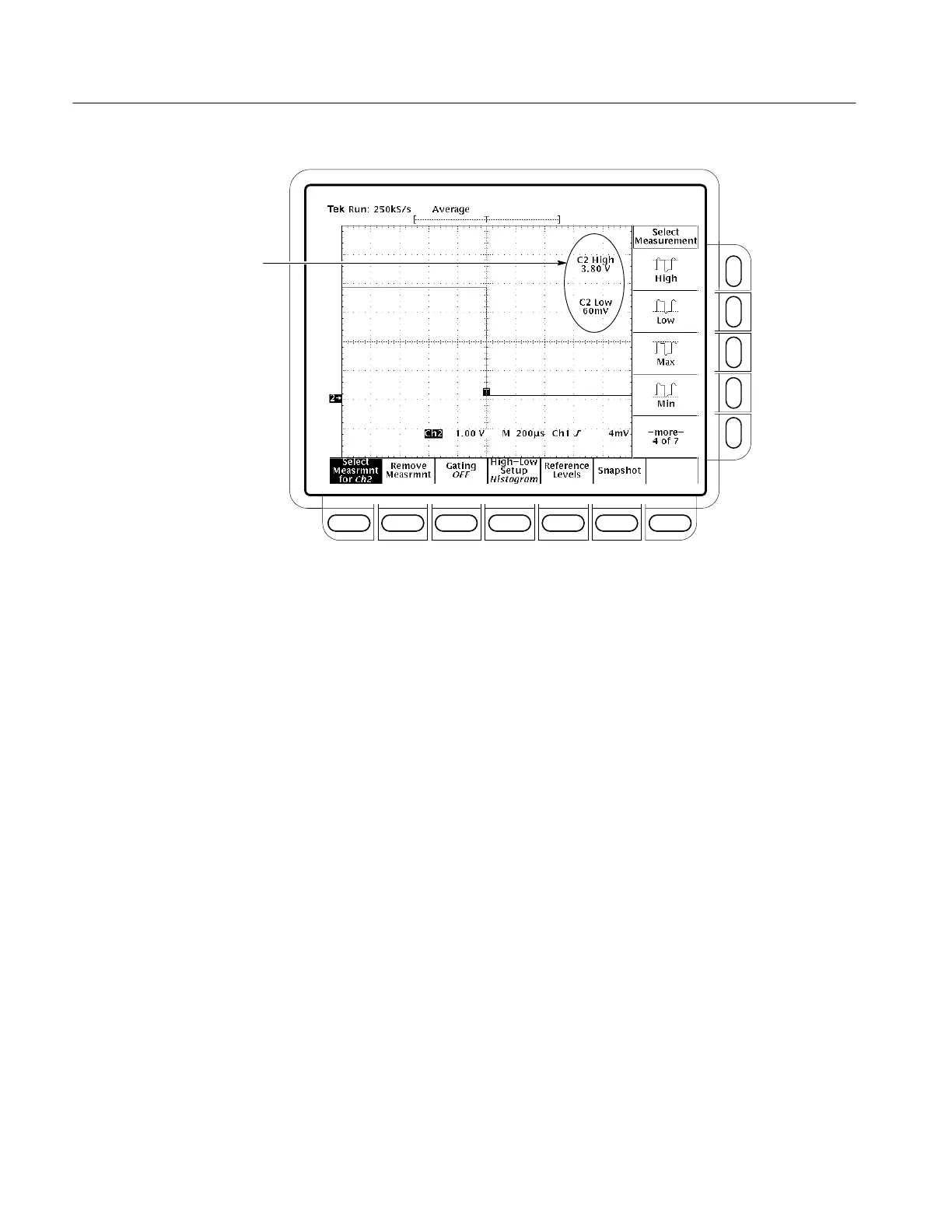
Figure 4–21: Measurement of Main Trigger Out Limits
d. Check Delayed Trigger output against limits: See Figure 4–21.
H Move the precision 50 W cable from the rear-panel Main Trigger
Output BNC to the rear-panel Delayed Trigger Output BNC.
H CHECK that the Ch2 High readout is ≥1.0 volt and that the Ch2
Low readout ≤0.25 volts.
H Enter high and low voltages on test record.
H Press the side-menu button to select the 1 MW setting.
H Press CLEAR MENU.
H CHECK that the Ch2 High readout is ≥2.5 volts and that the Ch2
Low readout is ≤0.7 volts.
H Enter high and low voltages on test record.
3. Confirm CH 3 (Ax1 on TDS 520B, 620B, 680B, and TDS 724A) output is
within limits for gain:
a. Measure gain:
H Move the precision 50 W cable from the rear-panel DELAYED
TRIGGER OUTPUT BNC to the rear-panel SIGNAL OUT BNC.
 Loading...


