Appendix E: Probe Selection
E–4
TDS 684A, TDS 744A, & TDS 784A User Manual
precisely connect your instrument to your device-under-test. These probes have
the same electrical characteristics as high speed, active probes but use a smaller
mechanical design.
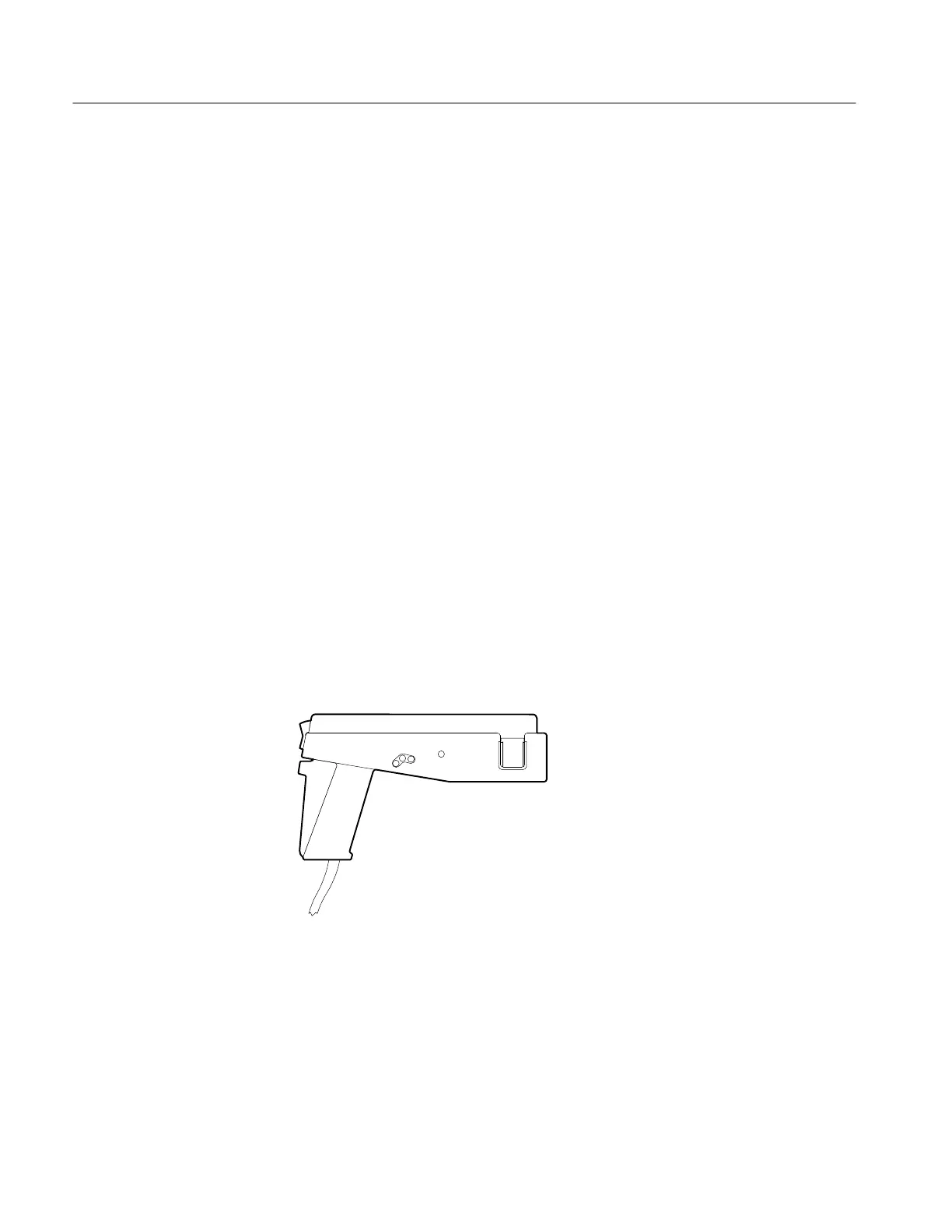
Current Probes
Current probes enable you to directly observe and measure current waveforms,
which can be very different from voltage signals. Tektronix current probes are
unique in that they can measure from DC to 1 GHz.
Two types of current probes are available: one that measures AC current only
and AC/DC probes that utilize the Hall effect to accurately measure the AC and
DC components of a signal. AC-only current probes use a transformer to convert
AC current flux into a voltage signal to the oscilloscope and have a frequency
response from a few hundred Hertz up to 1 GHz. AC/DC current probes include
Hall effect semiconductor devices and provide frequency response from DC to
50 MHz.
Use a current probe by clipping its jaws around the wire carrying the current that
you want to measure. (Unlike an ammeter which you must connect in series with
the circuit.) Because current probes are non-invasive, with loading typically in
the milliohm to low W range, they are especially useful where low loading of the
circuit is important. Current probes can also make differential measurements by
measuring the results of two opposing currents in two conductors in the jaws of
the probe.
Figure E–2: A6303 Current Probe Used in the AM 503S Opt. 03
 Loading...


