Performance Tests
TDS 500B, 600B and TDS 700A Service Manual
4–35
H Press the front-panel button that corresponds to the channel you are
to confirm.
H Move the leveling output of the sine wave generator to the channel
you selected.
b. Match the trigger source to the channel selected:
H Press TRIGGER MENU. Press the main-menu button Source; then
press the side-menu button that corresponds to the channel selected.
c. Set its input impedance:
H Press VERTICAL MENU; then press the main-menu button
Coupling.
H Press the side-menu button to toggle it to the 50 setting.
d. Set the vertical scale: Set the vertical SCALE to one of the settings
listed in Table 4–4 not yet checked. (Start with the 100 mV setting.)
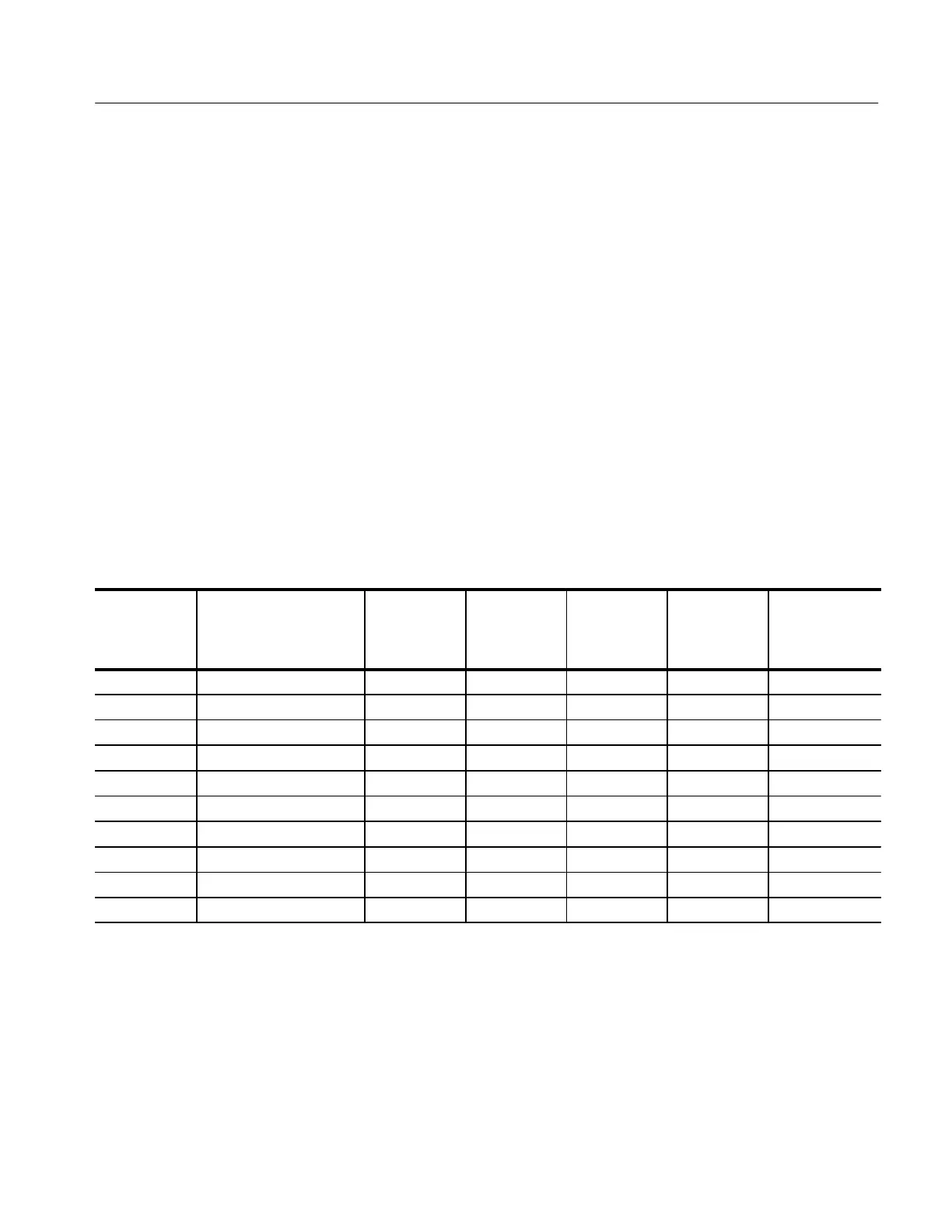
Table 4–4: Analog Bandwidth
Vertical Scale Reference Amplitude
Horizontal
Scale
TDS 680B,
684B, and
784A Test
Frequency
TDS 620B
and 644B
Test
Frequency
TDS 520B,
540B, 724A,
744A Test
Frequency
Limits
100 mV 600 mV (6 divisions) 1 ns 1 GHz 500 MHz 500 MHz ≥424 mV
1 V 5 V (5 divisions) 1 ns 1 GHz 500 MHz 500 MHz ≥3.535 V
500 mV 3 V (6 divisions) 1 ns 1 GHz 500 MHz 500 MHz ≥2.121 V
200 mV 1.2 V (6 divisions) 1 ns 1 GHz 500 MHz 500 MHz ≥848 mV
50 mV 300 mV (6 divisions) 1 ns 1 GHz 500 MHz 500 MHz ≥212 mV
20 mV 120 mV (6 divisions) 1 ns 1 GHz 500 MHz 500 MHz ≥84.8 mV
10 mV 60 mV (6 divisions) 1 ns 1 GHz 500 MHz 500 MHz ≥42.4 mV
5mV 30 mV (6 divisions) 1 ns 750 MHz 450 MHz 500 MHz ≥21.2 mV
2mV 12 mV (6 divisions) 1 ns 600 MHz 300 MHz 500 MHz ≥8.48 mV
1mV 6 mV (6 divisions) 1 ns 500 MHz 250 MHz 450 MHz ≥4.24 mV
e. Display the test signal: Do the following subparts to first display the
reference signal and then the test signal.
H Press MEASURE; then press the main-menu button Select
Measrmnt for CHx.
 Loading...


