Home
Tektronix
Test Equipment
TDS200 Series
Tektronix TDS200 Series Manual
4
of 1
of 1 rating
139 pages
Give review
Manual
Specs
To Next Page
To Next Page
To Previous Page
To Previous Page
Loading...
Maintenance
TDS1000
and
TDS2000
Series
Digital
Storage
Oscilloscopes
Service
Manual
6-
-
1
3
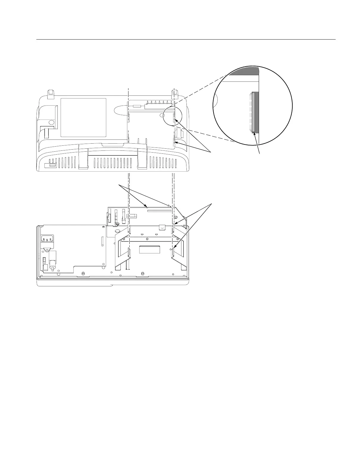
ESD
grounding
ears
are
properly
aligned
with
the
rear
case
slots
when
they
are
visible
in
approximately
one
half
the
width
of
the
slots.
Rear
case
slots
(4)
ESD
grounding
ears
(4)
Main
board
notches
Figure
6
-
-
5:
Aligning
the
oscilloscope
rear
case
91
93
Table of Contents
Table of Contents
6
General Safety Summary
12
Service Safety Summary
14
Environmental Considerations
16
Preface
18
Related Manuals
18
Specifications
20
Table 1- 1: Oscilloscope Specifications
22
Certifications and Compliances
29
Table 1- 2: Oscilloscope General Specifications
29
Operating Information
32
General Features
35
Installation
37
Power Cord
37
Security Loop
37
Figure 2- -1: Routing the Power Cord and Security Cable
37
Extension Modules
38
Figure 2- -2: Installing and Removing an Extension Module
38
Functional Check
39
Self Calibration
40
Default Setup
40
Table 2- -1: Default Settings
40
Theory of Operation
44
Figure 3- -1: Module-Level Block Diagram (Two Channel)
47
Figure 3- -2: Module-Level Block Diagram (Four Channel)
48
Main Board
49
Acquisition System
49
Input Signal Interface
50
Probe Compensation
50
External Trigger
50
Main Board Power
50
Power Supply
51
Display Module
51
Front Panel
51
Leds
52
Extension Modules
52
Performance Verification
54
Required Equipment
56
Test Record
57
Performance Verification Procedures
58
Self Test
58
Self Calibration
58
Check DC Gain Accuracy
58
Check Bandwidth
60
Check Sample Rate and Delay Time Accuracy
61
Check Edge Trigger Sensitivity
62
Adjustment Procedures
66
Required Equipment
68
Table 5- -1: Required Equipment
68
Adjustment Procedure
70
Enable the Service Menu
70
Figure 5- -1: Adjustment Setups
71
Adjustment Procedure
72
Table 5- -2: Adjustment Steps
73
Maintenance
78
Preparation
80
Preventing ESD
80
Inspection and Cleaning
81
General Care
81
Inspection and Cleaning Procedures
81
Table 6- -1: Internal Inspection Check List
82
Removal and Installation Procedures
84
Preparation
84
List of Modules
84
Summary of Procedures
85
Required Tools
85
Rear Feet
85
Table 6- -2: List of Procedures
85
Figure 6- -1: Removing the Rear Feet
86
Figure 6- -2: Installing the Rear Feet
87
Flip Feet
88
Figure 6- -3: Removing and Installing the Flip Feet
88
Front-Panel Knobs
89
Power Button
89
Rear Case
90
Figure 6- -4: Removing and Installing the Rear Case
90
Figure 6- -5: Aligning the Oscilloscope Rear Case
92
Front Feet
93
Figure 6- -6: Removing and Installing the Front Feet
93
Figure 6- -7: Removing the Power Supply Module
94
Power Supply Module
95
Figure 6- -8: Installing the Power Supply Module
95
Internal Assembly
96
Figure 6- -9: Removing and Installing the Internal Assembly
96
Display Cable
98
Figure 6- -10: Removing the Display Cable
98
Figure 6- -11: Installing the Display Cable
99
Front-Panel Cable
100
Figure 6- -12: Removing and Installing the Front-Panel Cable
100
Main Board Module
101
Figure 6- -13: Main Board Removal
102
Display Module
103
Figure 6- -14: Removing the Display Module
103
Figure 6- -15: Installing the Display Module
104
Front-Panel Module
105
Figure 6- -16: Removing the Front-Panel Module
105
Figure 6- -17: Installing the Front-Panel Module
106
Keypad
107
Front Case
107
Figure 6- -18: Removing and Installing the Keypad
107
Troubleshooting
110
Adjustment after Repair
110
Figure 6- -19: Oscilloscope Troubleshooting Tree (1
111
Figure 6- -20: Oscilloscope Troubleshooting Tree (2
112
Figure 6- -21: Oscilloscope Troubleshooting Tree (3
113
Troubleshooting Tree
114
PROBE COMP Output
114
Troubleshooting the Power Supply
114
Troubleshooting the Display
115
Troubleshooting the Backlight
117
Figure 6- -22: Measuring the Backlight Voltage
118
Troubleshooting the Front Panel
119
Troubleshooting the Main Board
122
Running Diagnostics
122
Troubleshooting Input Connections
122
Using the Error Log
123
Table 6- -3: List of Error Codes
123
Repackaging Instructions
125
Packaging
125
Storage
125
Figure 7- -1: TDS1000 and TDS2000 Series Block Diagram
129
Replaceable Parts
130
Parts Ordering Information
132
Module Servicing
132
Using the Replaceable Parts List
133
Abbreviations
133
Table 8- -1: Parts List Column Descriptions
133
Mfr. Code to Manufacturer Cross Index
134
Table 8- -2: Manufacturers Cross Index
134
Table 8- -3: Replaceable Parts List
135
Figure 8- -1: Exploded Diagram
138
Table 8- -4: Replaceable Standard Accessories
139
Table 8- -5: Replaceable Optional Accessories
139
Other manuals for Tektronix TDS200 Series
User Manual
207 pages
Programmer's Manual
250 pages
4
Based on 1 rating
Ask a question
Give review
Questions and Answers:
Need help?
Do you have a question about the Tektronix TDS200 Series and is the answer not in the manual?
Ask a question
Tektronix TDS200 Series Specifications
General
Brand
Tektronix
Model
TDS200 Series
Category
Test Equipment
Language
English
Related product manuals
Tektronix TDS2002
207 pages
Tektronix TDS2012
207 pages
Tektronix TDS2014
207 pages
Tektronix TDS2022
207 pages
Tektronix TDS2024
207 pages
Tektronix TDS2022B
137 pages
Tektronix TDS2024B
137 pages
Tektronix TDS2014B
137 pages
Tektronix TDS2000C series
161 pages
Tektronix TDS210
346 pages
Tektronix TDS3034B
166 pages
Tektronix TDS 754D
376 pages

 Loading...

