Performance Ve rification
5. Adjust the v ert
ical position knob for the DC line to position the line in the
center of the screen.
6. Enter the volt
age o n the voltmeter and on the oscilloscope into the spreadsheet
in the appropriate columns, B and C.
7. Repeat step
s 4 through 6 for the values of 1.76 V through 0 V.
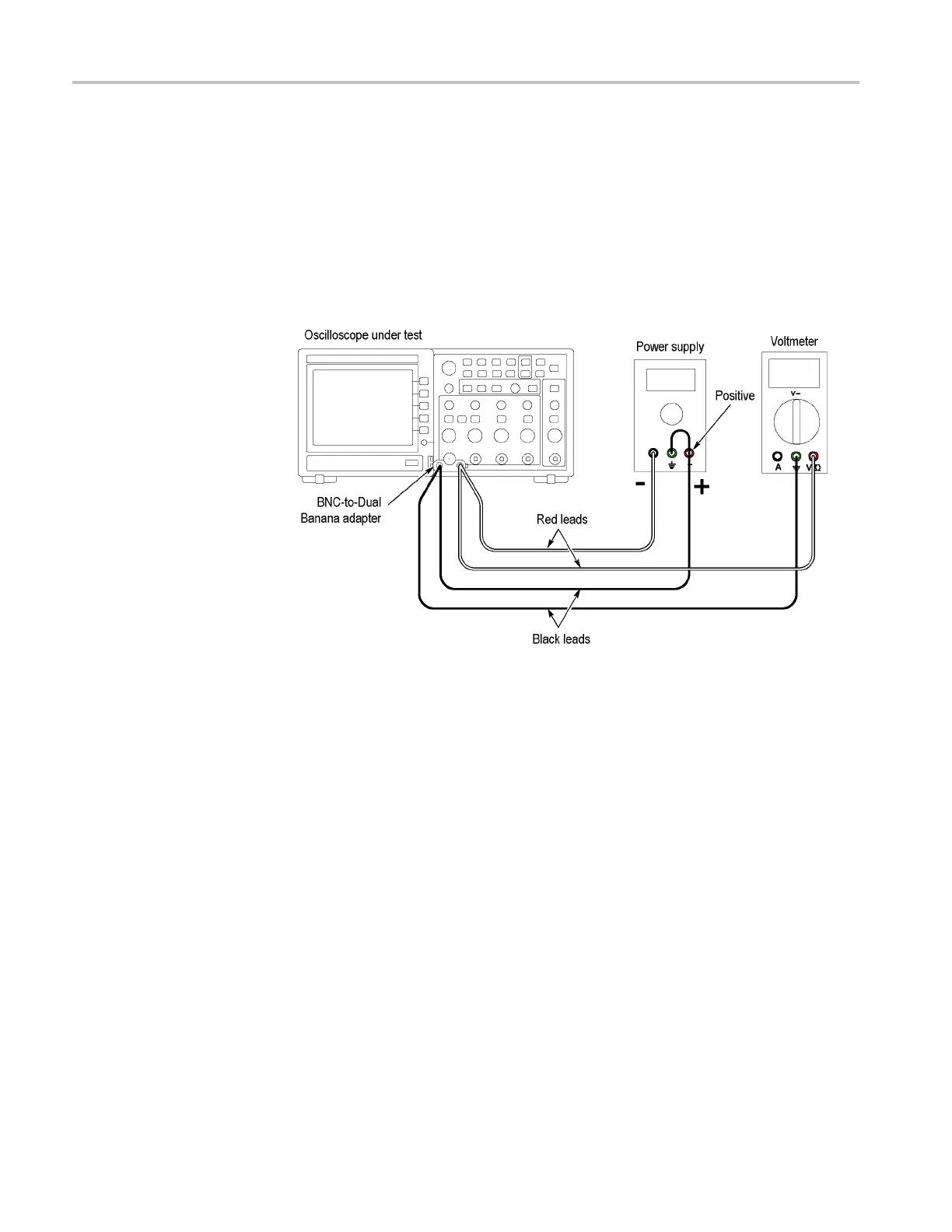
8. Swap the connections to the positive terminal of the power supply with those
at the negat
ive terminal as shown in the following figure:
9. Repeat steps 4 through 6 for the values of -0.04 V through -1.8 V.
10. Enter the Minimum Margin number (cell I16) for the channel tested in the
test record.
11. Repeat steps 1 through 10 for all input channels.
4–12 TDS2000C Series Oscilloscope Service Manual
 Loading...

