Getting Acquain
tedwithYourInstrument
Connecting Input Signals
Option SD/HD Setup 1
Setups 1A and 1B are the preferred setups for testing 3-wire component analog video signals ( Y/G, Pb/B, P r/R) with the
composite syn
c signal on Y/G . These setups use the Sync Pickoff accessory to derive the trigger signal from the Y/G signal
on CH1. The triggering source is set to Channel 4. This configuration provides more accurate low-level noise measurements
(below -60 dB at 30 MHz bandwidth) than setup 2.
This type of connection allows you to take more accurate noise measurements on CH1 while triggering on CH4, without
adding additi
onal cabling between CH1 and CH4. The additional cabling could adversely impact frequency response and
multiburst measurements.
To achieve the best frequency response and multiburst measurements, the 75 Ω termination should be c onnected as close to
the input connector as possible, as shown in the setup illustration.
There are two ways to connect the Sync Pickoff to the VM Serie s system. One way c onnects the Sync Pickoff directly to the
input and the
other way connects through a T-connector a ttached to a 75 Ω termination. Which method you use depends
on the Sync Pickoff version you are using.
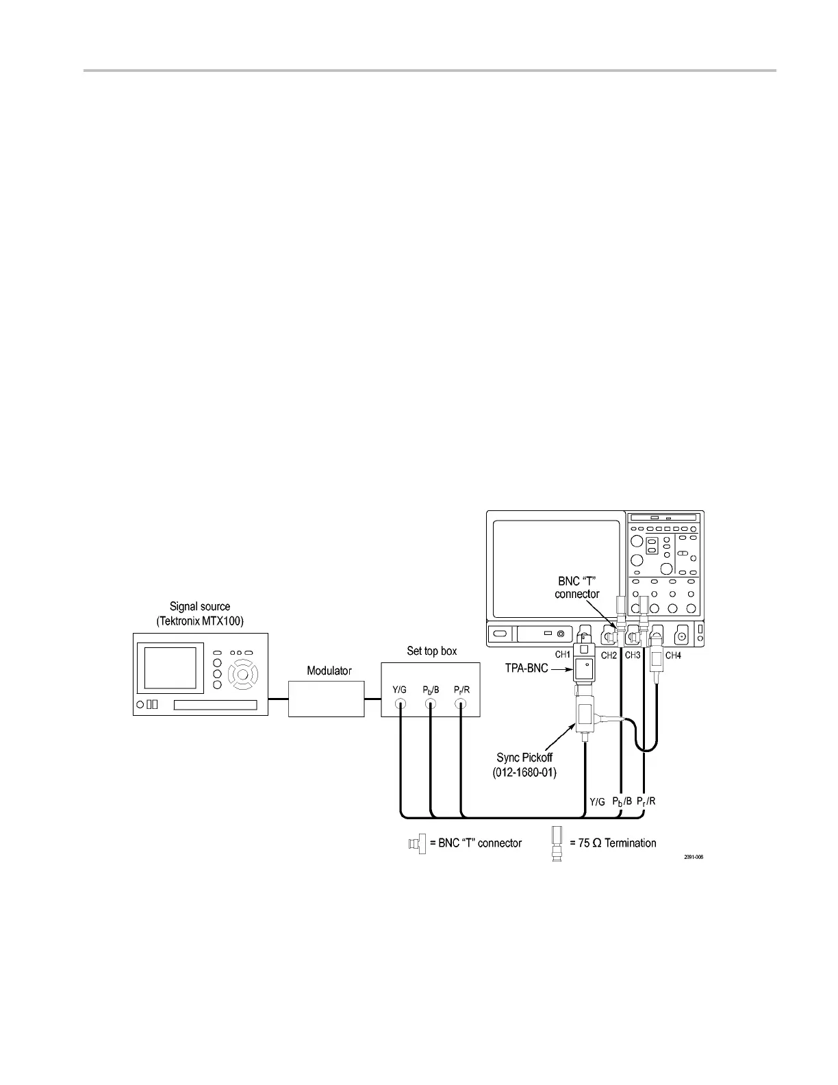
Setup 1A - Three-Wire Analog Video with Composite Sync for Sync Pickoff 012-1680-01. Ifyouareusinga
012-1680-01 Sync P ickoff (contains internal 75 Ω termination), connect the Sync Pickoff directly to the VM Series system
CH1 input (using a TPA-BNC adapter for VM6000 and DPO7000 Series instruments) as shown in the following illustration. If
you are using a 012-1680-00 Sync Pickoff (requires external 75 Ω termination), use the illustration shown in Setup 1B.
Connecting to a VM6000 / DPO7000 Series Instrument.
VM Series Video Measurement System Quick Start User Manual 9
 Loading...


