Packaging
information
3-6
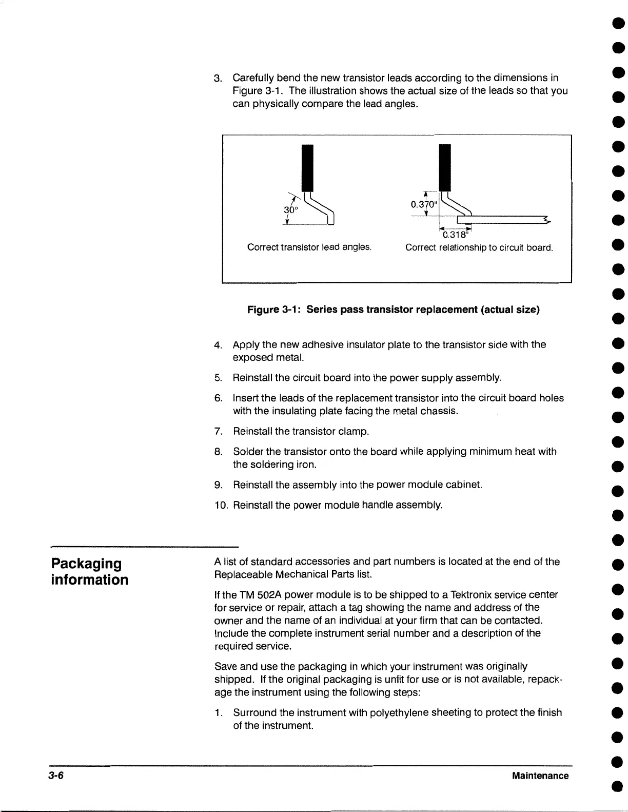
3. Carefully bend the new transistor leads according to the dimensions in
Figure 3-1. The illustration shows the actual size of the leads so that you
can physically compare the lead angles.
Correct transistor lead angles.
r
0.370"1
'( I
I
i,(0.318~:
Correct relationship to circuit board.
Figure 3-1: Series pass transistor replacement (actual size)
4. Apply the new adhesive insulator plate to the transistor side with the
exposed metal.
5. Reinstall the circuit board into the power supply assembly.
6. Insert the leads of the replacement transistor into the circuit board holes
with the insulating plate facing the metal chassis.
7. Reinstall the transistor clamp.
8. Solder the transistor onto the board while applying minimum heat with
the soldering iron.
9. Reinstall the assembly into the power module cabinet.
10. Reinstall the power module handle assembly.
A list of standard accessories and part numbers is located at the end of the
Replaceable Mechanical Parts list.
If the TM 502A power module is to be shipped to a Tektronix service center
for service or repair, attach a tag showing the name and address of the
owner and the name of an individual at your firm that can be contacted.
Include the complete instrument serial number and a description of the
required service.
•
•
•
•
•
•
•
•
•
•
•
•
•
•
•
•
•
•
•
•
•
•
•
•
•
•
Save and use the packaging in which your instrument was originally •
shipped. If the original packaging is unfit for use or is not available, repack- •
age the instrument using the following steps:
1. Surround the instrument with polyethylene sheeting to protect the finish
e
of the instrument.
Maintenance
•
•
•

 Loading...