Graphic Items and
Special Symbols
Used in This Manual
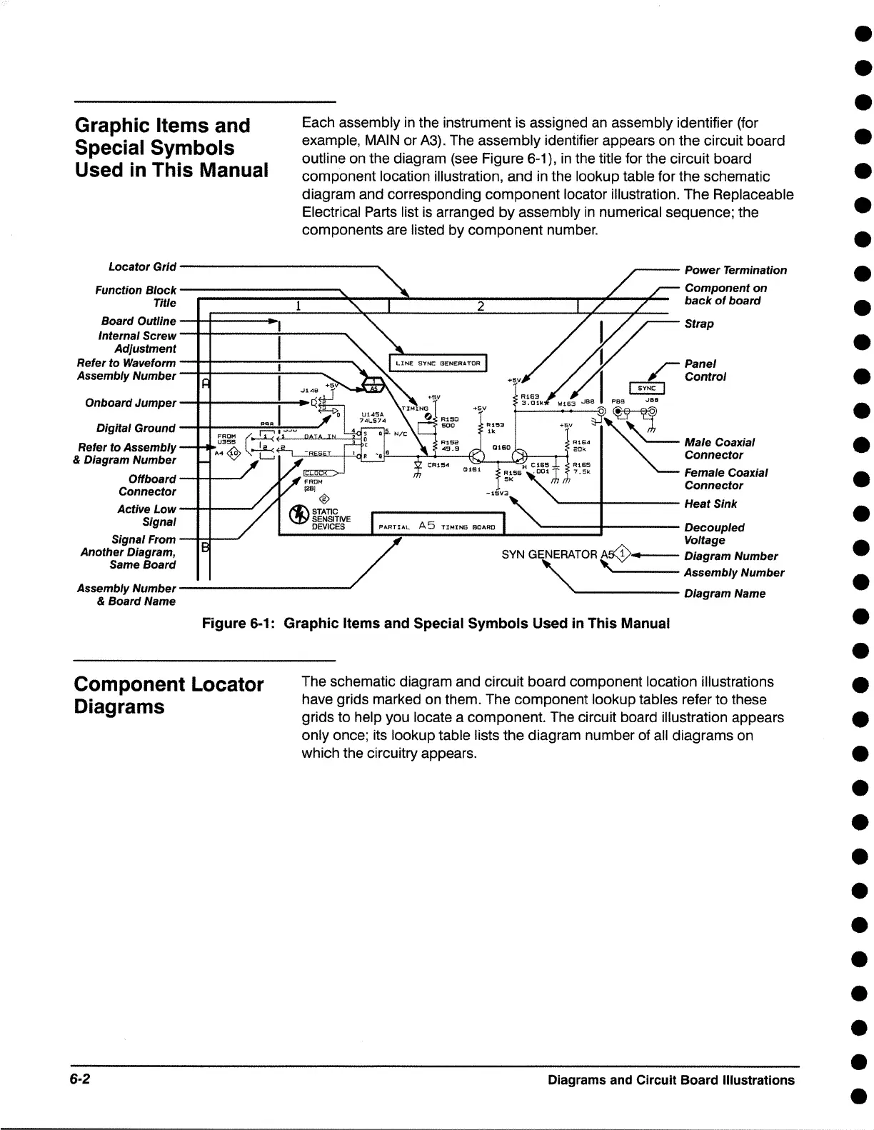
Each assembly in the instrument is assigned an assembly identifier (for
example, MAIN or A3). The assembly identifier appears on the circuit board
outline on the diagram (see Figure 6-1), in the title for the circuit board
component location illustration, and in the lookup table for the schematic
diagram and corresponding component locator illustration. The Replaceable
Electrical Parts list is arranged by assembly in numerical sequence; the
components are listed by component number.
Locator Grld----------- ...
--- Power Termination
Functlon Block---------
Tltle
Board Outline----- .. ,
Internal
Screw------------
Ad/ustment
Component on
back of board
Strap
Refer to Waveform
-t-+----+----
Assembly Number
w,
63
Jes I eea Jae
Digital Ground -t-+-----:==:+:::::::---'
a1s• "
~
Male Coaxial
-+5V ~~'-.,./,
Refer to Assembly
& Diagram Number
Offboard
---i.---
Connector
Active Low---i.---
,____....__7!::><J~~!:r::-:::-i""i
20
"
Connector
Female Coaxial
Connector
'----+---- Heat Sink
Signal .__ ____
..,__••-"T ... lA_L_A_5_Tl-MI-NG_a_o._Ro_._ ___ -... -_ -_ -_ -_ -_ -...::----- Decoupled
Signal From ___ _, / Voltage
Another Diagram,
SYN GENERATOR As(y, Diagram Number
Same Board , """
" ,.._ ___ Assembly Number
Assembly Number---------- . Diagram
Name
& Board Name
Figure 6-1: Graphic Items and Special Symbols Used in This Manual
Component Locator
Diagrams
6-2
The schematic diagram and circuit board component location illustrations
have grids marked on them. The component lookup tables refer to these
grids to help you locate a component. The circuit board illustration appears
only once; its lookup table lists the diagram number of all diagrams on
which the circuitry appears.
Diagrams and Circuit Board Illustrations
•
•
•
•
•
•
•
•
•
•
•
•
•
•
•
•
•
•
•
•
•
•
•
•
•
•
•
•
•
•
•
•

 Loading...