•
•
•
•
•
•
•
•
•
•
•
•
•
•
•
•
•
•
•
•
•
•
•
•
•
•
•
•
•
•
•
•
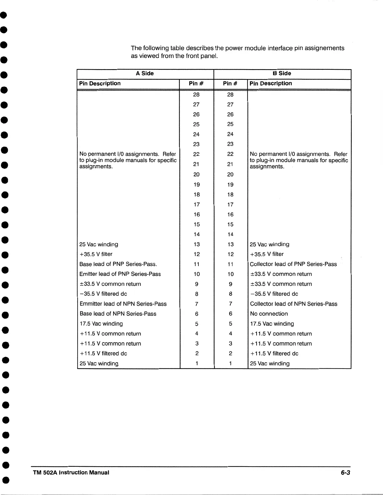
The following table describes the power module interface pin assignements
as viewed from the front panel.
A Side B Side
Pin Description
Pin#
Pin#
Pin Description
28 28
27
27
26
26
25 25
24 24
23
23
No permanent 1/0 assignments. Refer
22
22
No permanent 1/0 assignments. Refer
to plug-in module manuals for specific
21
21
to plug-in module manuals for specific
assignments. assignments.
20
20
19 19
18 18
17
17
16 16
15
15
14 14
25
Vac winding 13 13 25 Vac winding
+35.5 V filter 12 12 +35.5 V filter
Base lead of PNP Series-Pass.
11
11
Collector lead of PNP Series-Pass
Emitter lead of PNP Series-Pass
10 10 ±33.5 V common return
±33.5 V common return
9
9 ±33.5 V common return
-35.5 V filtered de
8 8
-35.5
V filtered de
Emmitter lead of NPN Series-Pass
7
7
Collector lead of NPN Series-Pass
Base lead of NPN Series-Pass
6
6
No connection
17.5 Vac winding
5
5
17.5
Vac winding
+ 11.5 V common return 4
4
+ 11.5 V common return
+ 11.5 V common return 3 3 + 11.5 V common return
+ 11.5 V filtered de 2
2
+ 11.5 V filtered de
25 Vac winding 1
1
25 Vac winding
TM 502A Instruction Manual 6-3

 Loading...