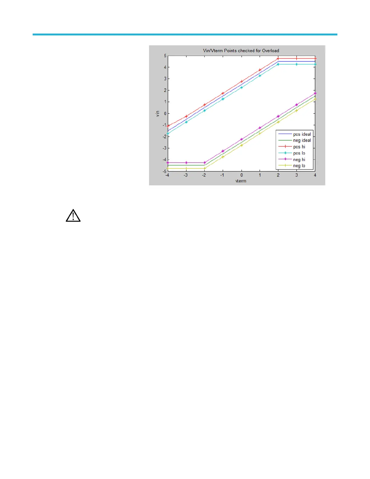
A graph of the operating limits of
the termination DC bias voltage
with respect to the input voltage
is shown for the P77C292MM
adapter. The hi and lo lines
represent the hysteresis sections
and the limits are the points
where the Status light turns on.
Probe tip information
Note: Probe tip ID is fully automatic. Manual selection is not required.
When the probe is first connected to the oscilloscope channel, the oscilloscope queries the probe for status information,
including the probe type, serial number, and the model number of the tip that is connected to the probe. The first time a
probe or probe tip is connected to a host oscilloscope, the probe and probe tip serial numbers are logged and the stored S-
parameters are downloaded. If the probe or probe tip are moved to another channel on the same oscilloscope, the logged
information is automatically processed without repeating the download process.
The Probe Controls described below are accessed using the Probe Controls selection from the oscilloscope Vertical menu.
Controls
Click on the Control button to display the Probe Controls screen. This screen displays a subset of the selections that are
available in the Probe Setup screen. The resulting shorter display height allows more room for the waveform display area.
Improving measurement accuracy
This section covers some of the features and characteristics of the probe that can affect the accuracy of your
measurements, and some steps that you can take to improve the performance of the probe.
Probe architecture
The probe measurement setup, as shown in the simplified drawing below, requires a host TekConnect FlexChannel
oscilloscope, a P7700 TDP7700 Series probe, and probe tips. An active probe tip includes a dual input buffer capable of
driving the 50 ohm signal path of the probe TekFlex connector and probe main cable. The dual input buffer is designed for
good matching of the A and B probe tip inputs to support differential measurements.
Basic operation
P7700 Series TriMode™ Probes 23

 Loading...


