around ground. The size of the probe input dynamic range depends on the probe tip that you are using, as shown in the
diagrams, and can also depend on the input mode selected. The probe input dynamic range limits are shown on the
oscilloscope display with a momentary annunciating, arrow-tipped line, when the vertical scale setting is large enough.
To set the offset voltages on the probe, you can use the controls in the Probe Setup screen panel. See Probe setup screen
panel on page 18.
To display the Probe Setup screen, select Probe Cal from the oscilloscope Vertical menu. You can also use the offset knobs
on the oscilloscope to set the offset voltage of the probe.
To display the Probe Setup panel, double tap the channel badge to open the configuration menu. Tap Probe Setup to open
the Probe Setup panel. Make changes to the offset.
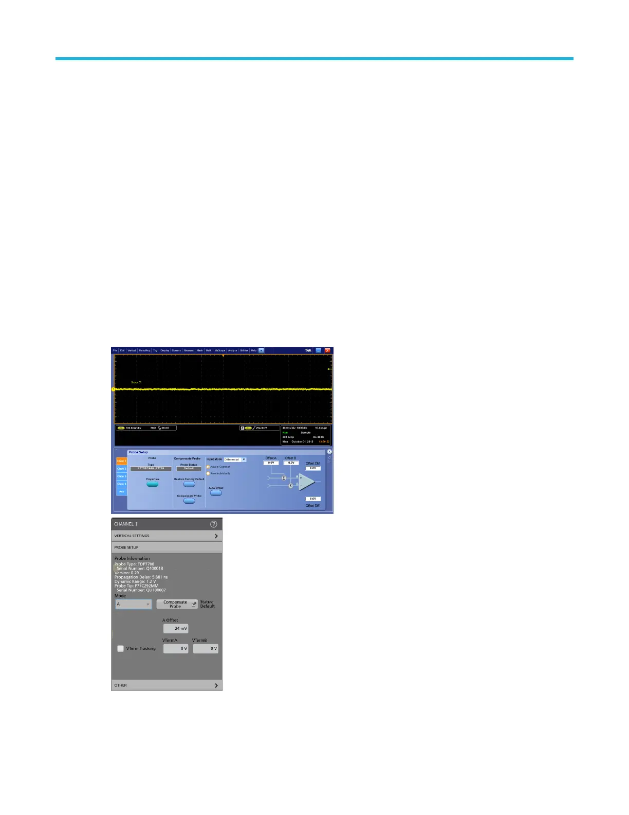
Probe setup screen panel
Use the Probe Setup screen to adjust the probe input settings for the measurement you are taking. To display the Probe
Setup screen, select Probe Cal from the oscilloscope Vertical menu. The Probe Setup screen can be used to select the
TriMode Input Mode setting and is also used to adjust the offset voltage controls for the probe tip A and B inputs.
Use the Probe Setup panel to adjust the probe input settings for the measurement you are taking. To display the Probe
Setup panel, double-tap the channel badge and then tap Probe Setup. The Probe Setup panel can be used to select the
TriMode Input Mode setting and is also used to adjust the offset voltage controls for the probe tip A and B inputs.
The following pages describe the controls and status fields in the Probe Setup screen panel.
Figure 3: Probe setup screen panel
Basic operation
P7700 Series TriMode™ Probes 18

 Loading...


