Getting Acquain
tedWithYourInstrument
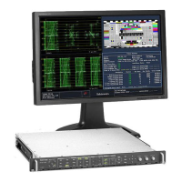
Ground Closure Interface Connector Pin Assignment
The ground closure interface (GCI) connector uses ground closures for remote control and indicating to external equipment
when alarms have occurred. The input of LTC is through the GCI connector. The GCI connector is a 15-pin D-type connector
with socket contacts.
Table 1: Remote Port
Characteristic Performance requirement Reference information
Connector Pin Assignments
Hex Binary
Pins 15,
14, 13,
12, 11,
10
Direct
mode
selection
Encoded
mode
selection
F 111111
none
No action
E XX1110 Preset 1 No action
D XX1101 Preset 2 No action
C
XX1100
SDI B
B XX1011 Preset 3
SDI A
A XX1010 No action
9 XX1001 No action
8 XX1000 Preset 8
7
XX0111 Preset 4 Preset 7
6 XX0110 Preset 6
5
XX0101 Preset 5
4 XX0100 Preset 4
3 XX0011 Preset 3
2 XX0010 Preset 2
1 XX0001 Preset 1
0 XX0000 Unused
N/A
101111 Preset 5
N/A
1GND(In)
2 Reserved (I/O)
3 Reserved (I/O)
4 Reserved (In)
5 Reserved (In)
6GND(In)
7TimeCodePositive(LTCIn)
8 Time Code Negative (LTC In)
9 Ground Closure (Alarm Out)
10 Preset 1 (In)
11 Preset 2 (In)
12 Preset 3 (In)
13 Preset 4 (In)
14 Preset 5 (In)
15 Preset 6 (In)
N/A
011111 Preset 6
N/A
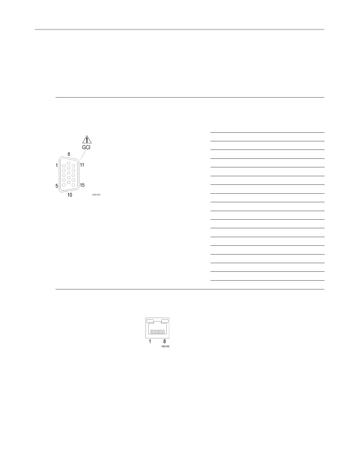
Ethernet Connector
The instrument provides a 10/100
BaseT Ethernet interface. The
Ethernet connector is a standard
RJ-45 connector.
WFM4000 and WFM5000 Waveform Monitors User Manual 13

 Loading...