AFA4000/1 Airflow Monitor / p.45
5.2.2 SM7 airflow sensor
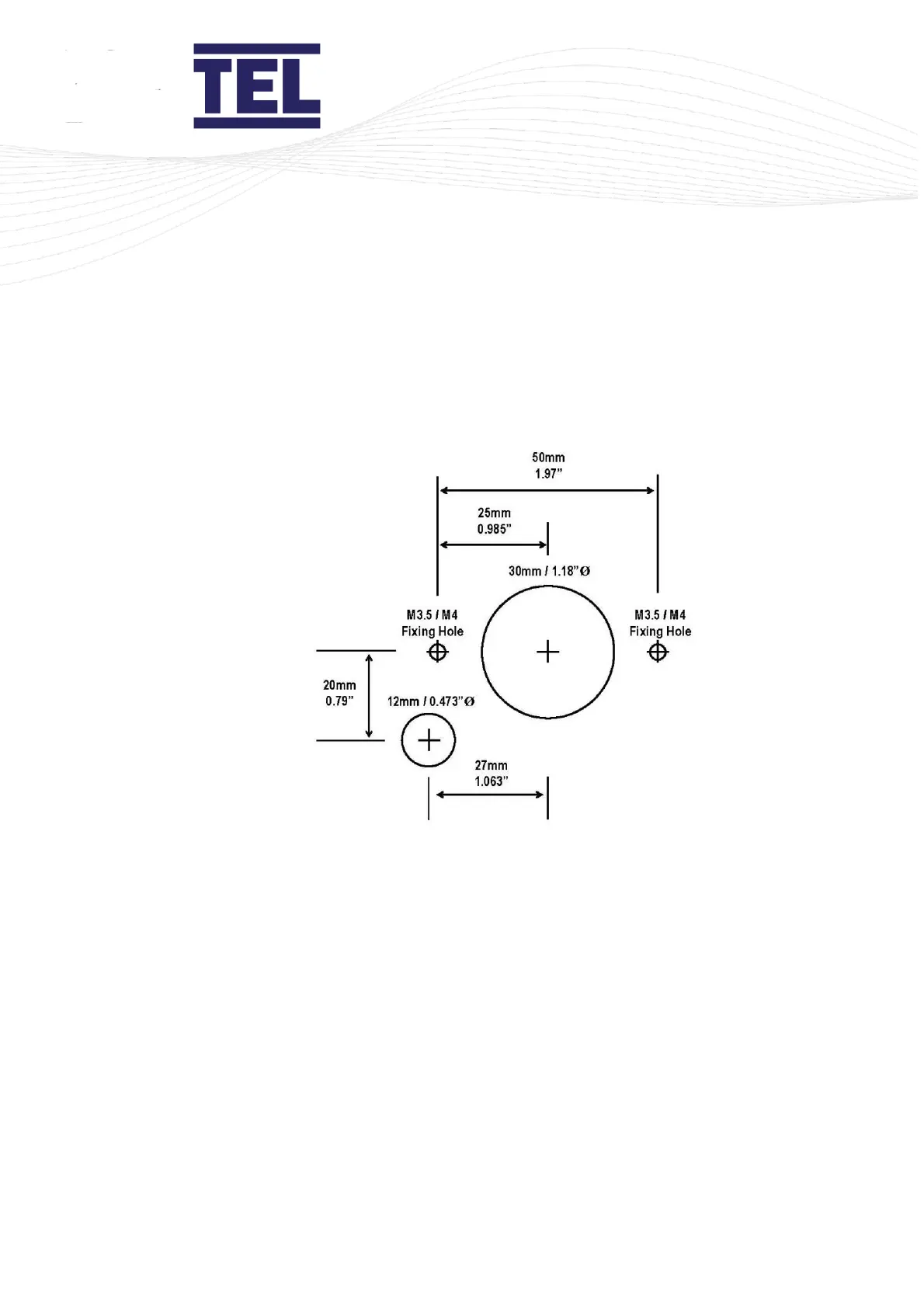
1. Use the cut-out details provided with the sensor (Figure 19) to cut-out and drill the
holes in the fume cupboard for the SM7 sensor.
Make sure that the sensor fits into the cut-out before proceeding.
Figure 19: SM7 sensor cut-out template
Note: Print to A4. Do not scale or print to fit page.
5.3 Connections
1. Connect the power supply cable into the back of the AFA4000/1 (H in Figure 20) and
to the connection on top of the fume cupboard.
2. Connect the ‘telephone style’ airflow sensor plug-in cable to the sensor and the back
of the AFA4000/1 unit (J in Figure 20).
 Loading...