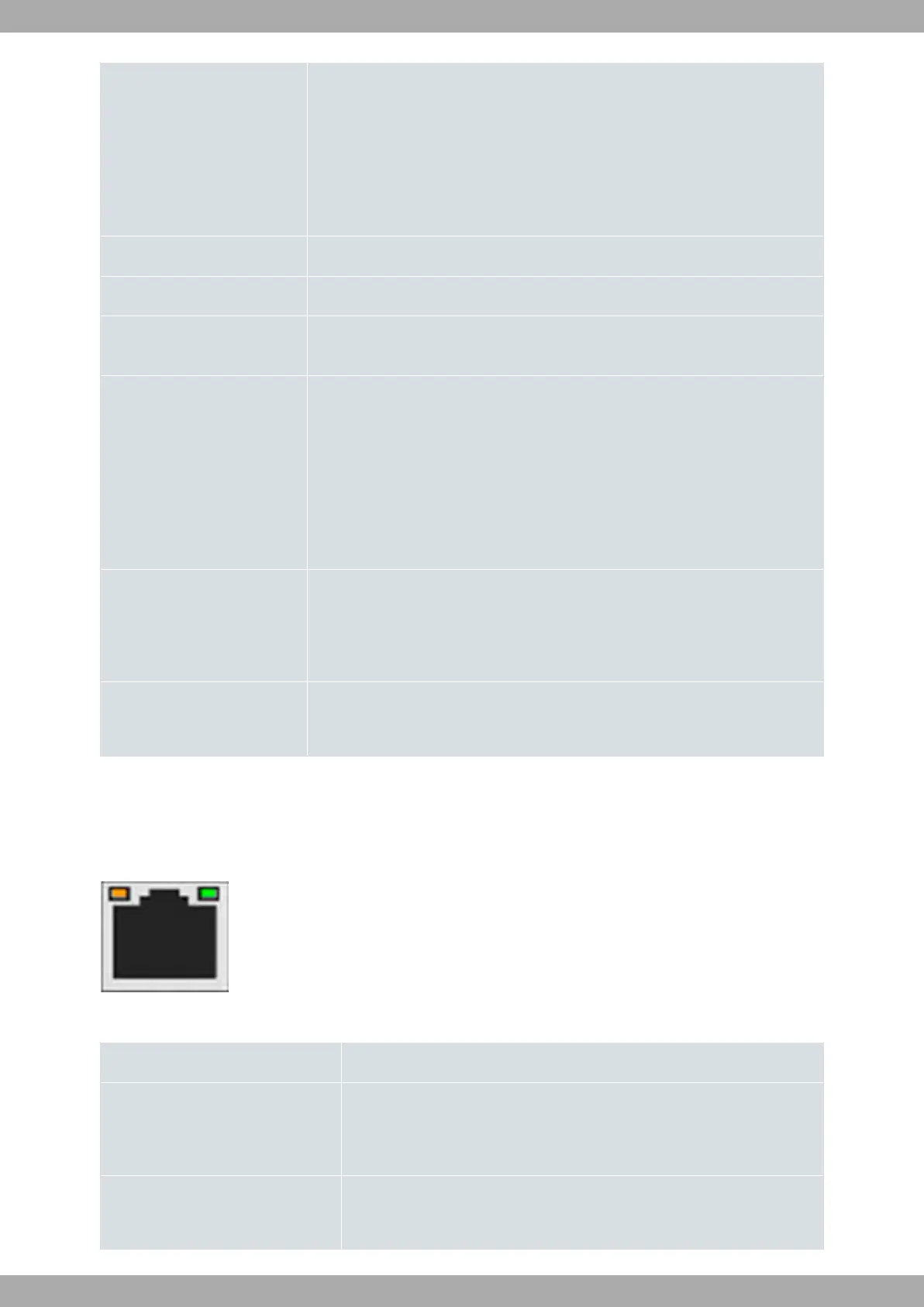
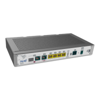
D 4-port Gigabit Ethernet Switch (LAN1 to LAN4).
For more information on the LAN interface, refer to:
- 4-port Ethernet switch connections on page 12
- LAN connectors on page 21
- LAN interface on page 23
E LED PWR (Power). Refer to on page for more information.
F LED WLAN (WLAN Status). Refer to LEDs on page 5 for more information.
G RST. Reset button. For further information on how the reset button works, please
see RST button on page 11.
H Aux. Provides access to the Teldat M2 local console for configuration and monit-
oring purposes.
For more information on the Aux connector, refer to:
- Connecting for configuration on page 13
- Configuration connector on page 22
- Configuration interface on page 26
I Power source connection (DC IN).
Refer to Power source on page 10 for more information on Power connection and
Power supply on page 26 for power specifications applicable to theTeldat M2
device.
J Kensington security slot
For further information, please see on page
In addition to the foregoing, the front panel also has LEDs linked to the LAN and WAN Ethernet interfaces.
3.1.1.1 LEDs
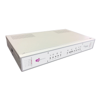
The following figure shows the router's WAN-1 LED indicators:
Fig. 3: WAN-1 LEDs
WAN-1 Ethernet LED indicators
LED Description
Green
Copper status
- Steady: 10/100/1000M link established.
- Blinking: Transferring data.
Yellow Fiber status:
- Steady: 1000M link established.
Teldat S.A.
3 Components and Power Supply
Teldat M2/M2L 5