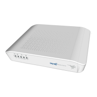
SIM-1 Off -> SIM-1 not used.
ON -> SIM-1 in use.
SIM-2 Off -> SIM-2 not used.
ON -> SIM-2 in use.
GPS
(Depending on
the model)
GPS Status Off -> GPS not available or not configured.
Green -> GPS coordinates have been acquired. Blinking: NMEA
data.
Amber -> Bad quality (HDOP).
Red -> Error.
Cloud Cloud Information Off -> No Cloud configuration.
Green -> Registering /connecting to the Cloud.
Amber -> Connected to the Cloud. Blinking: traffic exchange with
the Cloud controller.
Red -> Cloud registration error.
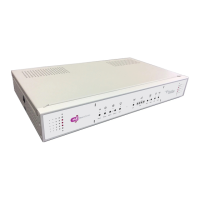
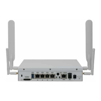
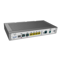
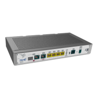
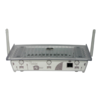
3.1.2 Rear Panel
The following figure shows the rear panel. Here you will find the majority of the M8-Smart router connectors.
Fig. 16: Rear panel
The following table provides information on each connector, as well as a description:
Rear panel elements
Item Description
A
Function.
B RST. Reset button. For further information on how the reset button works, please
see RST Button on page 13.
C 4-port Gigabit Ethernet switch.
For more information about the LAN interface, refer to:
- 4-port Ethernet switch Connections on page 14
- LAN Connector (Switch) on page 29
- LAN Interface on page 31
D Eth WAN-1 Base-T. WAN Gigabit Ethernet.
For more information about the WAN interface, refer to:
Teldat S.A.
3 Components and Power Supply
M8-Smart 7