English
TS6213
3
2 Product description and connections
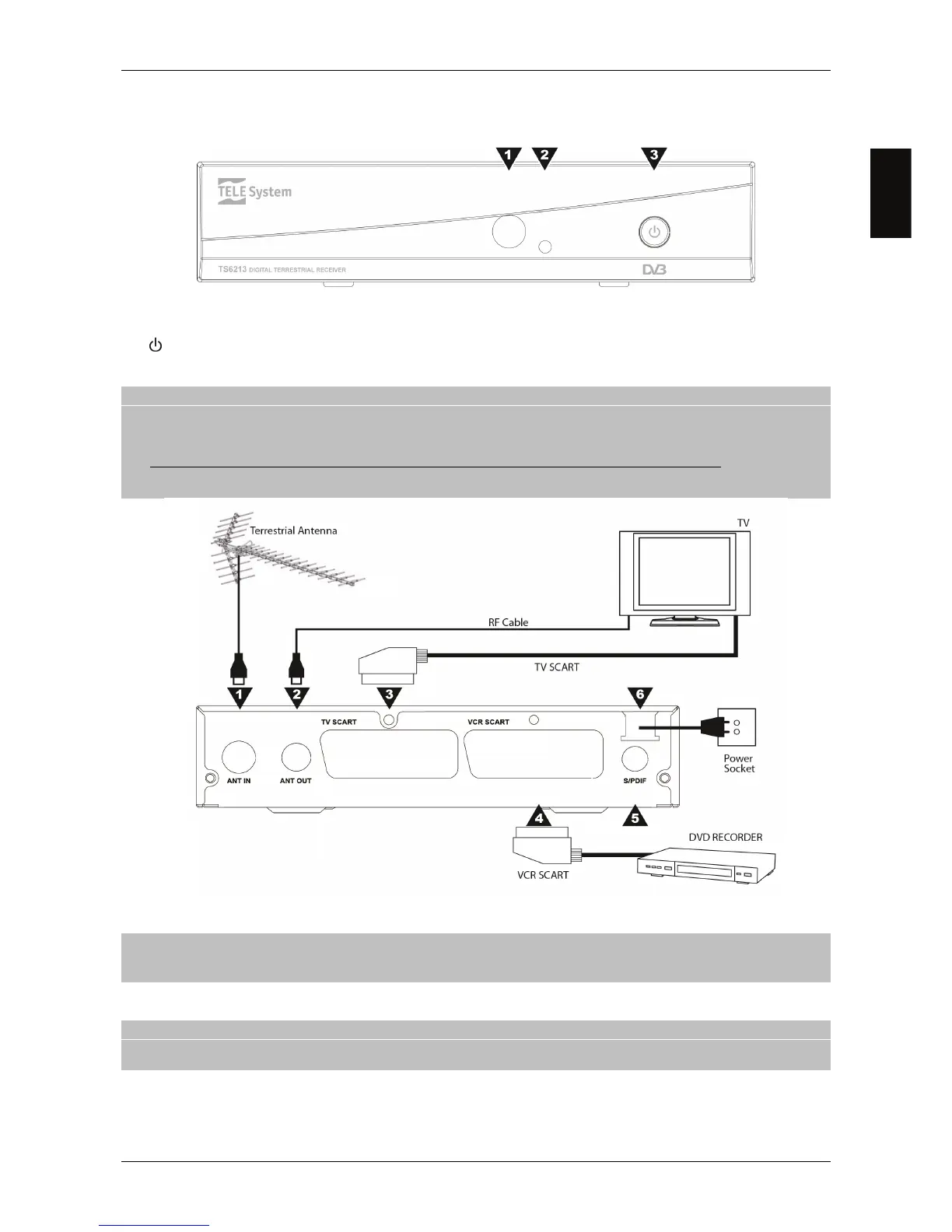
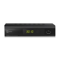
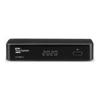
2.1 Front Panel
1. IR Infrared sensor for remote control.
2. LED Standby status indicator (Green=On, RED=stand-by).
3.
ON / Stand-by button.
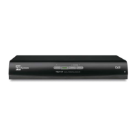
2.2 Rear panel and connections
CAUTION
It is good practice to connect the receiver with other appliances (e.g. TV, VCR, HI-FI, etc.) and the antenna before
plugging in the mains lead. When the receiver is powered electrical voltage differences may be created when
plugging in the jacks, which may generate currents that could damage the appliances.
The direct audio-video connection with TV screen should always be used as a first operating test, since other more
complex connection sequences may give malfunctions that are not caused by faults or defects of the actual
appliances but by problems of incompatibility.
1. ANT IN Antenna Input.
2. ANT OUT Antenna TV loop through output.
CAUTION
For energy saving, during stand.by mode the ANT OUT is disabled by default, but it can be activated by setting On the
RF Loop parameter in the Installation - Power Control menu.
3. TV SCART Analogue audio-video output for connecting TV screen.
4. VCR SCART Auxiliary analogue audio-video socket.
CAUTION
The VCR SCART plug can be used as input for an external source (e.g. DVD player), but only in operative mode and by
pressing the VCR/DTV button of the remote control unit.
5. SPDIF Coaxial Digital Audio output for home-theatre amplifier.
6. POWER Power lead for 230V AC, 50Hz.