3
1
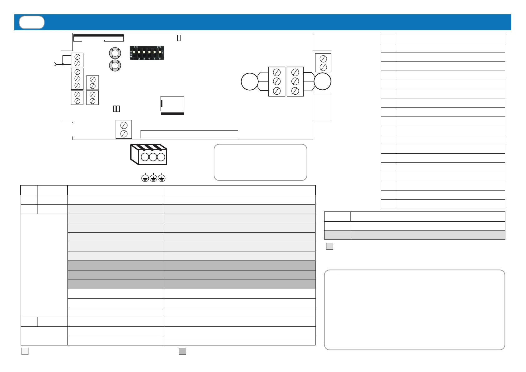
CONNECTIONS, ADJUSTMENTS AND CONTROL UNIT WARNINGS
RAIN
sensor
WIND
sensor
Aerial
TEMP. Sensor
= Weather sensor alarms (from LOW to HIGH priority) = MOTOR alarms
FIRST POWER ON: at rst power-on, the system is waiting to
be programmed with the memorization of at least one transmitter
(par. 3, page 8) and the conguration of the motors and relative
working time (see below).
MOTOR CONFIGURATION: Identify the correct product
application from the 3 given below and follow the relative
conguration procedure. Attention: if the wrong application is
selected, the conguration procedure must be repeated for the
correct application.
= It takes eect DURING conguration
DIP MEANING
1 - 2 - 3 Setting of wind sensor threshold (par. 4.2)
4 - 5 Motor control mode (par. 2.1, 2.2, 2.3)
Not
used
M1
M2
230Vac
M2
M1
12/24Vdc
LED
Temp.
Optional LED CARD
(only in TVPLA868AC2 version)
Memory
5A Fuse
230Vac
Power supply
L
N
2
1
19
18
17
16
P2
DIP switch
12
11
15
14
13
L3
L1
L2
22
23
P1
5
4
3
8
7
6
LED CARD power
supply (12-24Vdc)
Attention! The 230Vac input
of the electronic board and the
motors output are protected by
a 5A fuse.
Connection of
Earth wires (GND).
M1
M2
230Vac
M2
M1
12/24Vdc
LED
Temp.
M1 M2 GND
LED COLOUR STATUS MEANING
L1 RED ON Power ON
L2 RED One ash every 10 s Survival alarm (par. 4.1)
Two ashes every 10 s Wind alarm (par. 4.2)
Three ashes every 10 s Snow alarm (par. 4.3)
Four ashes every 10 s Rain alarm (par. 4.4)
Five ashes every 10 s After Rain (par. 4.5)
Six ashes every 10 s Temperature alarm (par. 4.6)
Six quick ashes Built-in motor limit switch activated
Seven quick ashes Unexpected absorption of one motor in synchronized mode
Eight quick ashes Safety limit switch
One quick ash every second Survival deactivate (par. 4.1)
One quick ash every 2 s Rain sensor is deactivated (par. 4.4)
One quick ash every 3 s Temperature sensor is deactivated (par. 4.6)
L3 BLUE ON Synchronized mode activated
One ash every second Synchronized mode activated (during conguration)
One ash every 2 s Independent mode activated (during conguration)
1 230 Vac (LIVE)
2 230 Vac (Neutral)
3 MOTOR 1 (CLOSE)
4 MOTOR 1 COMMON
5 MOTOR 1 (OPEN)
6 MOTOR 2 (OPEN)
7 MOTOR 2 COMMON
8 MOTOR 2 (CLOSE)
11 WIND SENSOR (BROWN)
12 WIND SENSOR (BLUE)
13 RAIN SENSOR (WHITE, +12Vdc)
14 RAIN SENSOR (BLUE, SIGNAL)
15 RAIN SENSOR (YELLOW, GND)
16 AERIAL RF
17 AERIAL GND
18 TEMPERATURE SENSOR (BLACK)
19 TEMPERATURE SENSOR (WHITE)
22 LED CARD POWER SUPPLY(GND)
23 LED CARD POWER SUPPLY (12-24Vdc)
 Loading...