Do you have a question about the Teledyne 316RA and is the answer not in the manual?
Details features that are not standard on all models of the Series 316.
Explains the working principle and features of the Micro-Fuel Cell used for trace oxygen measurement.
Describes the sample path flow control system including valves and purging procedures.
Lists essential safety precautions and handling instructions before and during analyzer installation.
Specifies the recommended installation location and environmental considerations for the analyzer.
Details the required fittings and sealant for connecting sample and calibration gas lines.
Describes the optional manifold for introducing sample or calibration gas and recommended valve types.
Advises on reducing sample pressure and recommends regulators for specific pressure conditions.
Outlines procedures for sampling at low or zero pressure, involving a downstream pump.
Specifies requirements for safely venting the analyzer's exhaust to the atmosphere.
Guides on making customer wiring connections at terminal strips on the motherboard.
Explains the preset output signal ranges and recommendations for using shielded cable for interconnection.
Details the optional alarm contacts, their rating, and how they are set to energize based on set points.
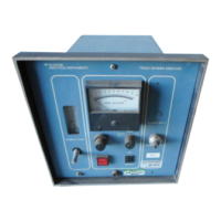
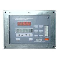
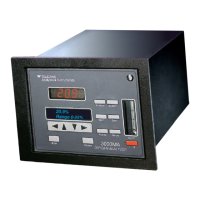
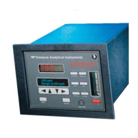
Identifies and describes the function of each control and indicator on the analyzer's front panel.
Instructs on checking and adjusting the mechanical zero of the analog meter before powering on.
Guides on the initial power-on procedure, setting the range, and observing meter response.
Details the steps for starting sample flow after establishing power, including opening valves and setting flow rate.
Explains how to set the optional alarm points using front panel controls based on desired ppm levels.
Provides guidance on adjusting sample flow, determining calibration frequency, and normal operation.
Describes the procedure to minimize air diffusion when cutting off sample flow for shutdown.
Step-by-step instructions for checking and replacing the unit's fuse if it fails to power on.
Details how to identify a faulty sensor and the procedure for its replacement.
Advises on ordering and storing spare Micro-Fuel Cells to ensure availability and maintain cell life.
Outlines the warranty period for the Micro-Fuel Cell and conditions for claims or credits.
Provides troubleshooting steps for when the analyzer's meter shows no reading.
Offers solutions for inaccurate readings, including checking zero, flow rate, leaks, and sensor.
Addresses issues with the analyzer failing to calibrate correctly with ambient air.
Provides guidance for high initial readings upon electrical start-up, suggesting stabilization or sensor replacement.
Lists detailed technical specifications for the Series 316 Trace Oxygen Analyzer.
Enumerates the available part numbers and descriptions for replacement components.
Provides a list of reference diagrams and their associated document numbers for various analyzer versions.
Identifies the product name, manufacturer, and contact information for the sensors.
Details the physical and chemical properties of the electrolyte (Potassium Hydroxide) and lead.
Describes potential fire, explosion, and reactivity hazards associated with the Micro-Fuel Cells.
Outlines health risks, exposure limits, symptoms, and other health hazards related to the sensor components.
Provides immediate first aid measures for eye, skin, ingestion, and inhalation exposure.
Offers guidance on protective clothing, clean-up, cell replacement precautions, and disposal.
| Brand | Teledyne |
|---|---|
| Model | 316RA |
| Category | Analytical Instruments |
| Language | English |