Do you have a question about the Teledyne 3300TA and is the answer not in the manual?
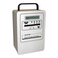
Introduces the Teledyne Electronic Technologies Analytical Instruments Model 3300TA trace oxygen analyzer.
Lists the key features and capabilities of the Model 3300TA analyzer.
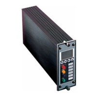
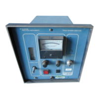
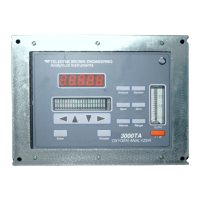
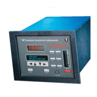
Describes the front panel controls, display, and indicators of the analyzer.
Details the electrical input/output connectors and ports on the rear panel.
Introduces the two main subsystems of the analyzer: Analysis Unit and Control Unit.
Explains the principles of operation for the Micro-Fuel Cell sensor.
Describes the internal construction and components of the Micro-Fuel Cell.
Details the chemical reactions that generate current in the Micro-Fuel Cell.
Explains how sample pressure affects oxygen diffusion and measurement accuracy.
Discusses the linear input/output curve and sensor failure detection method.
Covers the microprocessor, signal processing, and power supply circuitry.
Instructions for unpacking and inspecting the analyzer unit and accessories for damage.
Guidelines for selecting a suitable installation location and mounting the control unit.
Details rack mounting instructions for the 3300TA Control Unit.
Details the correct orientation and procedure for installing the Micro-Fuel Cell.
Describes the rear panel connectors, power input, and fuse block.
Outlines how to connect sample, span, and vent gas lines to the analyzer.
Provides guidance for vacuum service pluming and flow rate adjustments.
Lists essential checks to perform before powering on the instrument.
Outlines configuration steps: defining ranges, setting alarms, and calibration.
Explains how to use the front panel buttons for setup and calibration.
Guides on adjusting the HI and LO analysis ranges for optimal measurement.
Steps to set the full-scale value for the least sensitive analysis range.
Steps to set the full-scale value for the most sensitive analysis range.
Instructions for adjusting alarm setpoints for high or low conditions.
Details configuring Alarm 1 as high or low and setting its actuation point.
Details configuring Alarm 2 as high or low and setting its actuation point.
Notes that alarm contacts are used for power failure indication, not cell failure.
Explains how to switch between fixed and autoranging operation modes.
Provides the step-by-step procedure for calibrating the analyzer.
Explains how the LED display shows concentration in percent or ppm units.
Step-by-step guide on how to safely replace a blown fuse in the unit.
Information on when to replace the Micro-Fuel Cell sensor and associated procedures.
Discusses symptoms of a failing sensor and acceptable offset levels.
Guidance on ordering, storing, and handling spare Micro-Fuel Cells.
Provides detailed instructions for safely removing a spent or damaged Micro-Fuel Cell.
Step-by-step guide for installing a new Micro-Fuel Cell into the analyzer.
Outlines the warranty terms and conditions for the Micro-Fuel Cells.
Lists the technical specifications of the Model 3300TA analyzer.
Provides a list of available spare parts with part numbers and descriptions.
Lists available reference drawings for the analyzer's diagrams.
Explains symbols used and provides MSDS contact information.
Details physical and chemical data for the Micro-Fuel Cell electrolyte and components.
| Measurement Principle | Electrochemical |
|---|---|
| Sensor Type | Electrochemical |
| Applications | semiconductor manufacturing |
| Technology | Electrochemical |
| Operating Temperature | 0 to 50°C |
| Operating Pressure | Atmospheric |
| Outputs | 4-20mA, RS-232 |