Do you have a question about the Teledyne 3010TA and is the answer not in the manual?
General description of the 3010TA Trace Oxygen Analyzer, its architecture, and purpose.
Lists common industrial applications for the 3010TA analyzer.
Explains how model and part numbers identify specific analyzer configurations.
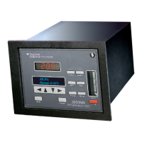
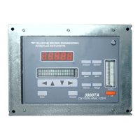
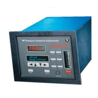
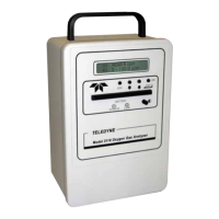
Introduces the Model 3010TA Analyzer Control Unit and its role within the system.
Details the front panel layout, including display, buttons, and access door for the Control Unit.
Describes electrical connectors, inputs, and outputs on the rear panel of the Control Unit.
Explains the signal path from sensor to digital conversion within the Control Unit.
Describes the instrument's temperature control to prevent freezing in cold environments.
Covers unpacking procedures and mounting options like flush panel and rack mount.
Details power, analog outputs, alarm, and communication connections on the rear panel.
Outlines steps for testing the installed Control Unit and its interconnected Analysis Unit.
Explains navigation and data input using the analyzer's front panel buttons.
Covers accessing system settings like Auto-Cal, password, logout, and self-test.
Details procedures for performing zero and span calibration of the analyzer.
Provides instructions for replacing fuses in the Control Unit.
Explains how to initiate and interpret self-diagnostic test results for the Control Unit.
Identifies key internal components within the Control Unit chassis.
Instructions for cleaning the outside surfaces of the Control Unit.
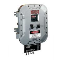
Introduces the Model 3010T Analysis Unit and its function as a remotely controlled instrument.
Describes the gas inlet and outlet connections on the Analysis Unit's external panel.
Details power, fuse, and signal connections on the Analysis Unit's internal electrical panel.
Explains the electrochemical principles of operation for the Micro-Fuel Cell sensor.
Details the physical structure and components of the Micro-Fuel Cell transducer.
Describes the chemical reactions that generate current in the Micro-Fuel Cell.
Discusses the effect of sample pressure and linear calibration curves for the cell.
Explains different cell classifications like Hydrogen Service and L-2C for specific applications.
Details the gas delivery system designed to transport sample gas to the cell.
Covers unpacking procedures and bulkhead mounting for the Analysis Unit.
Guides on connecting gas lines, including restrictor selection for different services.
Details connections for voltage selector, power, fuses, and remote probe interfaces.
Instructions on observing the flowmeter to monitor gas flow past the sensor.
Discusses calibration gases and refers to Control Unit procedures for calibration.
Details running and interpreting self-diagnostic tests for the Analysis Unit.
Outlines routine checks and lists major components of the Analysis Unit.
Detailed steps for removing, storing, handling, and installing a new Micro-Fuel Cell.
Instructions for replacing fuses within the Analysis Unit's electrical panel.
Explains how to run and interpret self-diagnostic tests specific to the Analysis Unit.
Provides detailed technical specifications for the Model 3010TA analyzers.
Lists recommended spare parts for maintaining the instrument for two years.
Lists available outline, assembly, and wiring diagrams for the analyzer units.
Offers guidance on sample handling, pressures, and flow rate recommendations for analyzers.
| Technology | Electrochemical Sensor |
|---|---|
| Accuracy | ±1% of full scale |
| Resolution | 0.01 ppm |
| Measurement Type | Trace Oxygen |
| Range | 0-10 ppm to 0-25% O2 |
| Response Time | 90% in less than 10 seconds |
| Operating Temperature | 0 to 45°C |
| Outputs | 4-20 mA, RS-232 |
| Weight | 0.5 kg |