Assembly Cont’d
Make sure that your bench is clean and the PCB is not sitting on any cut off component leads. Connect supplied power cable to a
supply of 11-16 VDC. The dashed white lead on the supplied power cable is the + lead (center pin). The green LED should light.
Using your DMM, check for 5.0 VDC (+/- 0.25V) at pin 3 of U1 (the pin connected to C3). Monitor total current draw of LP-PAN
using the DMM or current meter on a power supply. Current draw should be 28mA. Power down.
Install the 1mH ceramic chokes (br-blk-red) one at a time, and check LP-PAN current draw as each one is added to verify no
unexpectedly high changes to total current draw. Expected total current draw is shown after each choke. If your values vary
significantly from these, check your work in the circuit affected by the most recently added choke. Refer to schematic.
L5 29mA
L7 31mA
L1 39mA
L2 41mA
L3 47mA
L6 53mA
Attach the four rubber feet to the bottom of the enclosure.
Install the PCB in enclosure using 3/16” black screws and ¼” standoffs. Loosely install the standoffs on the bottom, and then slide
the board into place, rear first. Attach the screws from the top while aligning the holes on the rear panel, then tighten the screws
underneath.
Install keycap on SW11. The enclosure top will be installed after calibration.
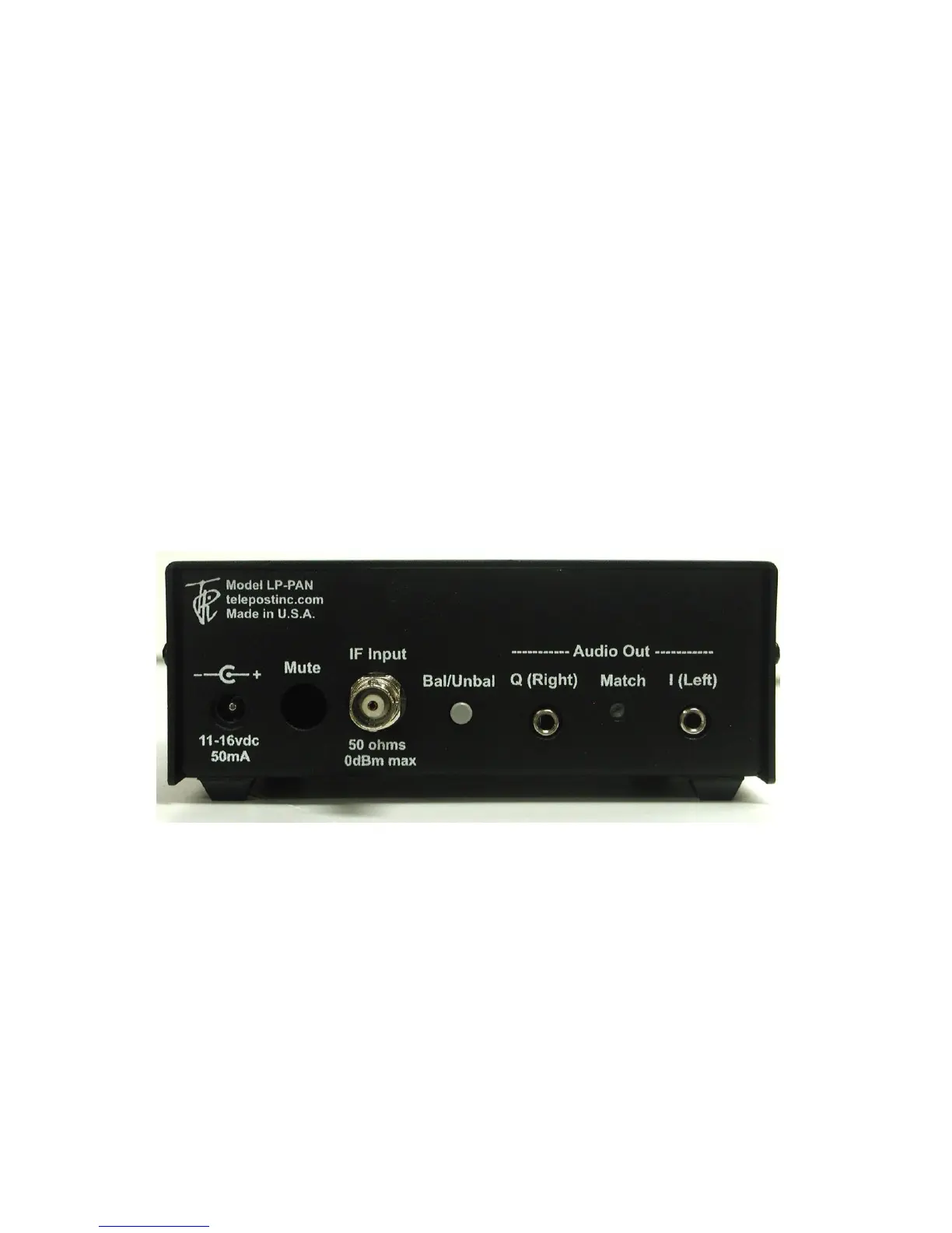
Connections…
Power: 11-16 VDC, center pin +, 2.5mm. The lead with the white stripe on the supplied cable is +. Power can be derived from a wall
wart, accessory power supply, RigRunner type manifold or the accessory power jack on the K3. In general, a supply with a linear
regulator will provide lower overall noise floor and fewer visible spurs on the panadapter display than a switched regulator will.
Mute: Gnd to mute. 5VDC. This will not be used in most installations, a software mute is provided by LP-Bridge / PowerSDR. See
PowerSDR Operation section of this manual for details.
IF Input: From rig. 8.215 MHz for Elecraft K3, 8.83 MHz fo Kenwood, 9.0 MHz for Orion (II).
Bal/Unbal: Out for balanced, In for unbalanced
I/Q Outputs: To sound card inputs
Match: Used to fine tune load balance between channels (Name changed to “Match” starting with serial #101 to better describe its
function).
 Loading...