Assembly Cont’d
Install all 0.1 uF caps (marked 104).
C2
C3
C8
C20
C33
C42
Install all .01 uF caps (marked 103).
C14
C16
C22
C24
C27
C29
C32
C37
Install remaining ceramic disc and SM caps, and the two trimmer caps.
C1 33pF ceramic disc (marked 33)
C12 18pF ceramic disc (marked 18) –For K2: 81pF (marked 81)
C13 10pF ceramic disc (marked 15) – For K2: 68pF (marked 68)
C30 47pF SM (marked 47)
C36 56pF ceramic disc (marked 56)
C40 0.001uF ceramic disc (102)
C34. 35 4-20pF trimmer cap
C21, 28 Not used on K3 or Orion – For Kenwood: 220pF (marked 221), For 10.7: 0.001uF (marked 102)
C41, 43 3300pF ceramic disc (marked 332) – For Kenwood/Orion: 2700pF (marked 272), For K2: 0.01uF, For 10.7:
0.001uF (marked 102)
Install D1 (LED)
Install Q1. Keep leads short.
Install U1. Keep leads short.
Install R29 (pot).
Install SW11
Install J3. You will need to clip off the two plastic tabs on the bottom of the connector off before installing. Latch the rear pin first for
strength, then solder the front pin.
Install J11
Install the three 2-pin and one 3-pin headers. Install a shorting jumper between pins
at JP2. Install a jumper on the ground pin only on JP1 & JP3. Install a jumper
between pins 2 & 3 of JP4 (the two toward the front of the board).
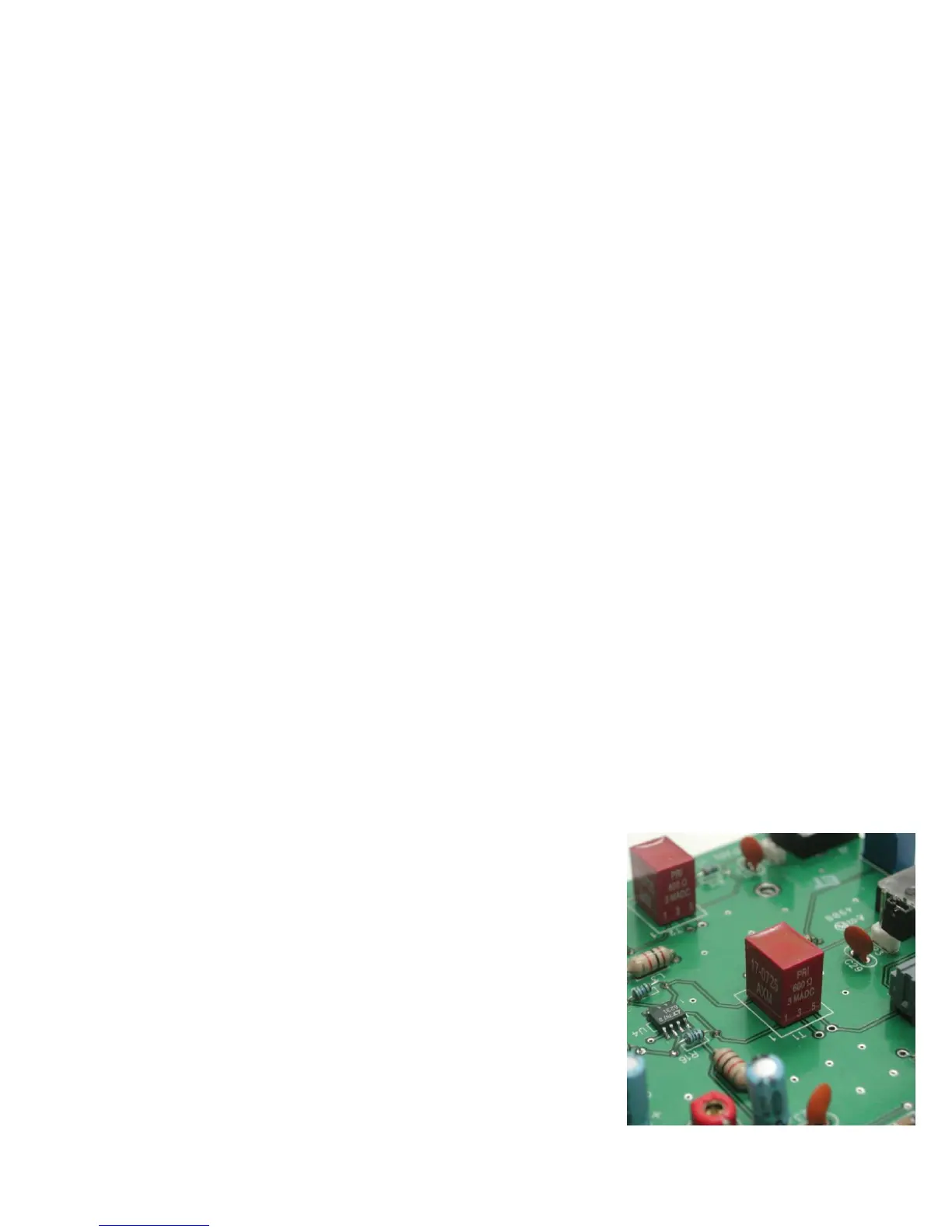
Install T1 and T2. Orient pin 1 near the silk-screened “1” marking, as shown.
Install R23 (pot)
Install crystal, Y1
Install the electrolytics, taking care with polarity. The “+” lead is the longer one, “-“
lead is marked with a black or white stripe, or blue semi-circle.
C15, 17, 23, 25, 38 1uF (25V)
C19 100uF (25V)
C26 10uF (25V)
Install J1