Assembly Cont’d
Step-by-step assembly instructions.
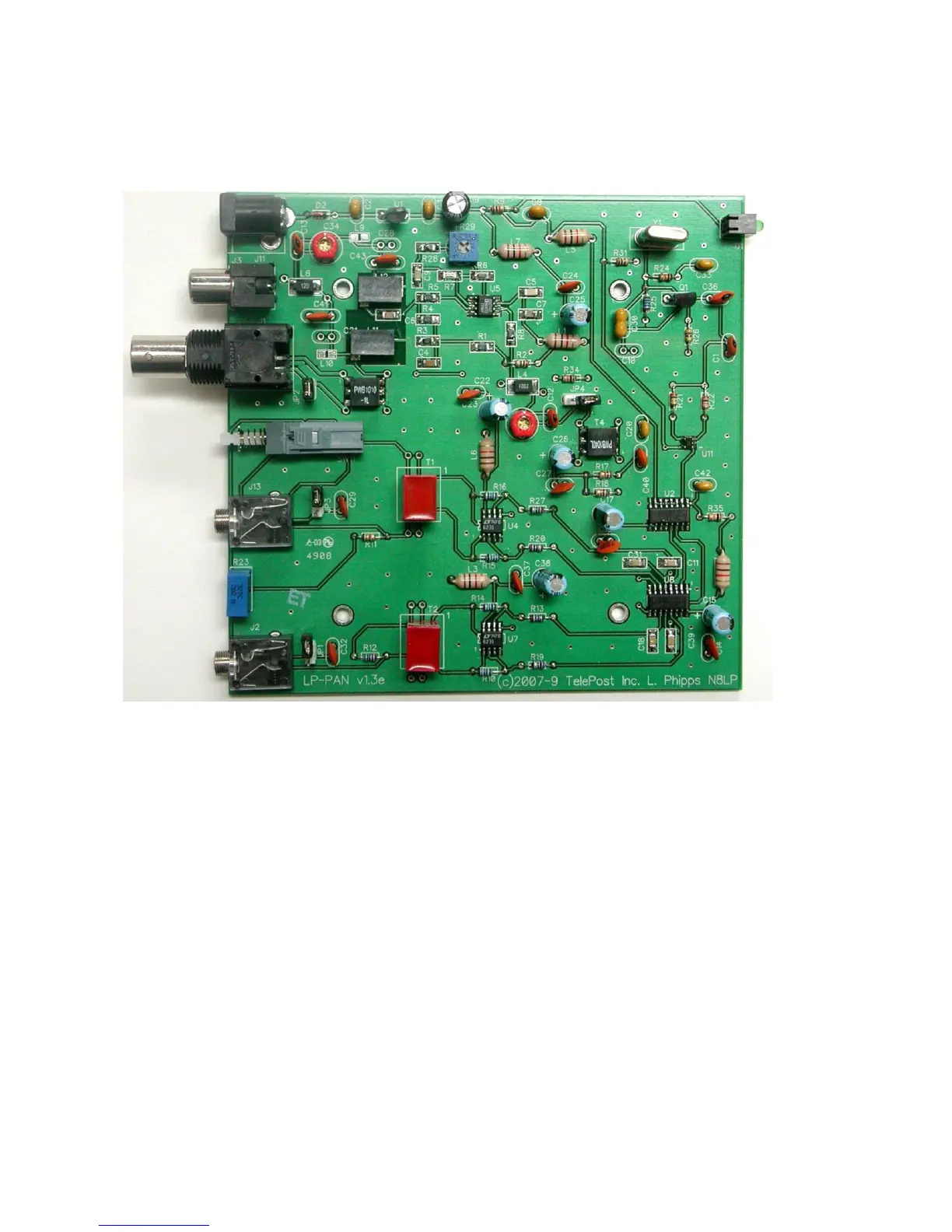
Below is a picture of the assembled PCB. The SMT parts come pre-installed. The component layout diagram on page 7 provides
another aid to component identification. Units after #309 will be ever so slighlty different… mainly in the area of C41 & C43.
It is recommended that you print at least this portion of the manual to allow for easy reference while building, and to allow you to check
off the steps as you complete them. Make sure your work area is static-free to avoid damage to the pre-installed SMT parts. It is also
advisable to wear an anti-static wrist band and grounded soldering iron. Refer to the parts placement graphic on page 7 or the above
picture for questions regarding parts placement.
Install resistors. Solder and clip leads after about six parts are installed to minimize clutter. If you are unsure of the colors used by
some of the manufacturers for the color code, especially the 1% parts, measure the value with a DMM. Occasionally, parts listed
as 5% will be supplied as 1% due to availability when ordering. Double check with DMM.
R2,31 10 ohm 1/8W res. (br-blk-bk)
R9,17,18,34 1K 5% 1/8W res. (br-blk-rd)
R10,14,15,16 1.1K 1% 1/8W res. (br-br-blk-br-br)
R11 1.5K 5% res. (br-grn-rd)
R12 2K 5% 1/8W res. (rd-rd-blk-br-br) or 2.2K 1% (rd-r-bk-br-br)
R13,19,20,27 22 ohm 1% 1/8W res. (rd-rd-bk-gld-br)
R21,22 2K 5% 1/8W res. (rd-bk-rd)
R24,35 10K 5% 1/8W res. (br-bk-or)
R25 27K 5% 1/8W res. (rd-viol-or)
R26 470 ohm 5% 1/8W res. (yel-viol-br)
Install the two audio jacks next. Solder the center lead first, so that you can adjust the jacks to be parallel with the board edge
before soldering the remaining pins.
Install D2. Follow polarity markings on PCB.