Telink TLSR8232 BLE SDK Developer Handbook
AN-19112700-E1 144 Ver.1.0.0
directly rebooted; the link layer can’t respond to Master with ack, and Master fails to
send data until timeout.
5) Read four bytes of Master Flash 0x20018~0x2001b to determine firmware size
which is realized by compiler. Suppose firmware size is 20k (0x5000), the value of
firmware 0x18~0x1b is 0x00005000, so the firmware size can be read from
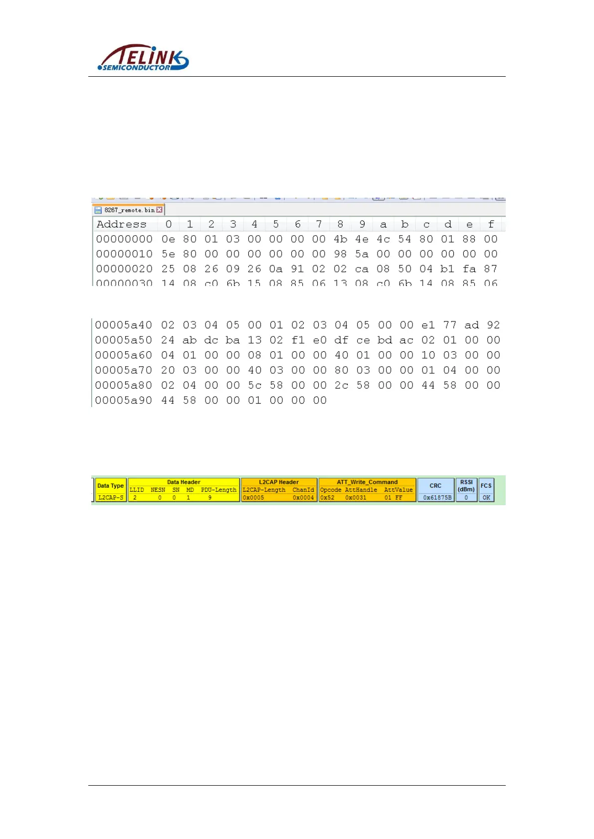
20018~0x2001b. As shown below, 0x18~0x1b of “5316_remote.bin” is
“0x00005a98”, so the firmware size is 0x5a98, i.e. 23192 bytes from 0 to 0x5a97.
Figure 6-5 Firmware: Starting Part
Figure 6-6 Firmware: Ending Part
6) Master sends an OTA start command “0xff01” to Slave, so as to inform it to enter
OTA mode and wait for OTA data from Master, as shown below.
Figure 6-7 Master Sends “OTA start”
7) Read 16-byte firmware each time starting from Master Flash 0x20000, assemble
them into OTA data packet, set corresponding adr_index, calculate CRC value, and
push the packet into TX FIFO, until all data of the firmware are sent to Slave. OTA
data format is used in data transfer: 20-byte valid data contains 2-byte adr_index,
16-byte firmware data and 2-byte CRC value to the former 18 bytes.
Note: If firmware data for the final transfer are less than 16 bytes, the remaining
bytes should be complemented with “0xff” and need to be considered for CRC
calculation.
The 5316_remote.bin as shown in Figure 6-5 and Figure 6-6 is taken as an example
to illustrate how to assemble OTA data.
Data for first transfer: “adr_index” is “0x00 00”, 16-byte data are values of addresses
0x0000 ~ 0x000f. Suppose CRC calculation result for the former 18 bytes is
“0xXYZW”, the 20-byte data should be:
0x00 0x00 0x0e 0x80 ... (12 bytes not listed)... 0x88 0x00 0xZW 0xXY