LE910Cx mPCIe Hardware Design Guide
1VV0301510 Rev. 13 Page 30 of 73 2021-07-07
Low-level input leakage current, no pull-up
High-level input leakage current, no pull-down
Table 14: Logic Levels Minimum and Maximum
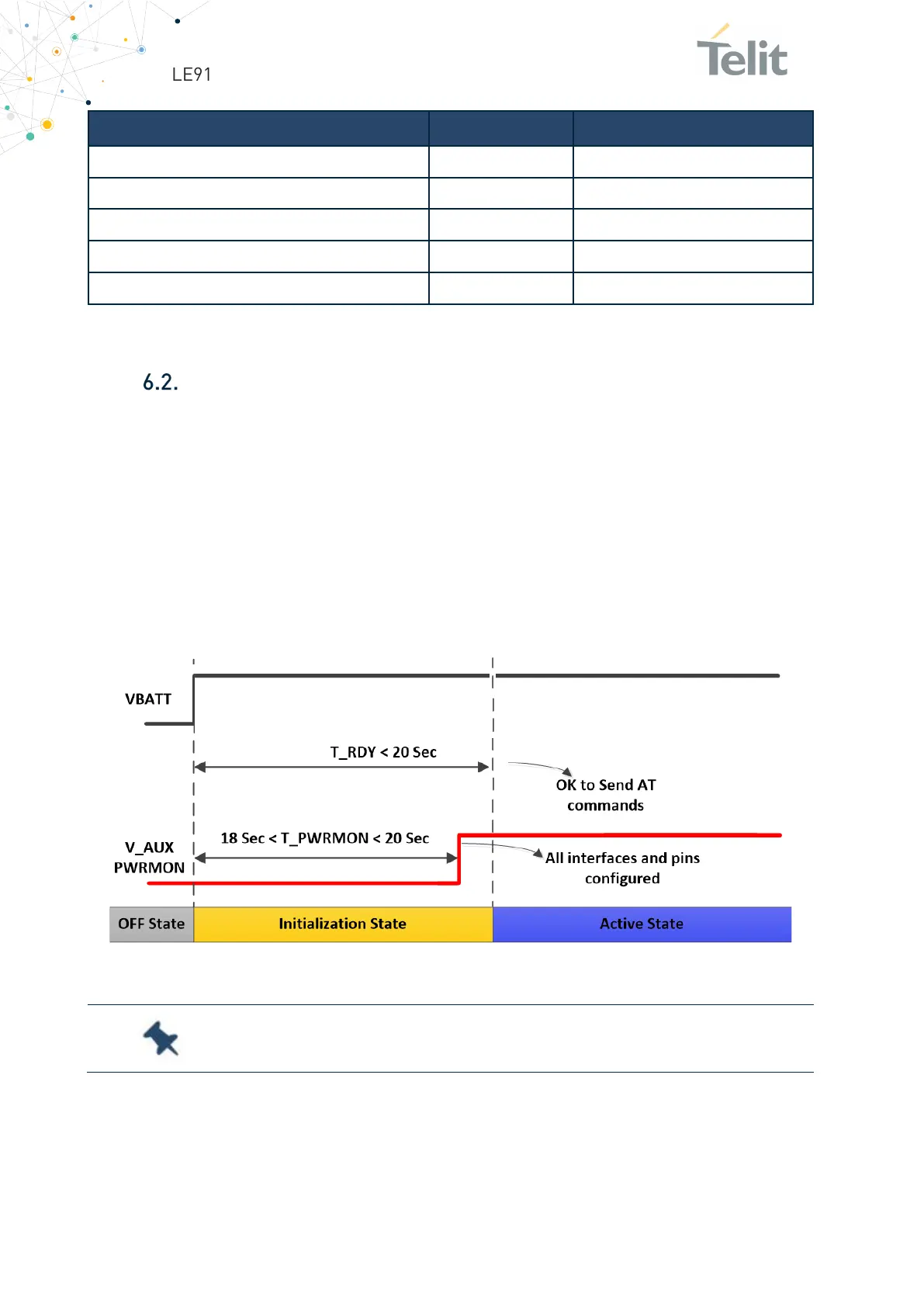
Power On
The LE910Cx-mPCIe will automatically power on as soon as VBATT is applied to the
module. The LE910Cx-mPCIe is not yet activated because the module SW initialization
process is still in progress internally. It takes some time to fully complete the HW and
SW initialization of the module. For this reason, it is impossible to access LE910Cx-PCIe
during the Initialization state. The VAUX / PWRMON pin will be then set at the high logic
level when the pins and interfaces are configured.
As shown below the LE910Cx-mPCIe becomes operational (in the Activation state) at
least 20 seconds after power is applied:
Figure 4: Operational LE910Cx-mPCIe
: To turn on the LE910Cx-mPCIe module, the W_DISABLE_N pin
must not be asserted low.
 Loading...


