LE910Cx mPCIe Hardware Design Guide
1VV0301510 Rev. 13 Page 36 of 73 2021-07-07
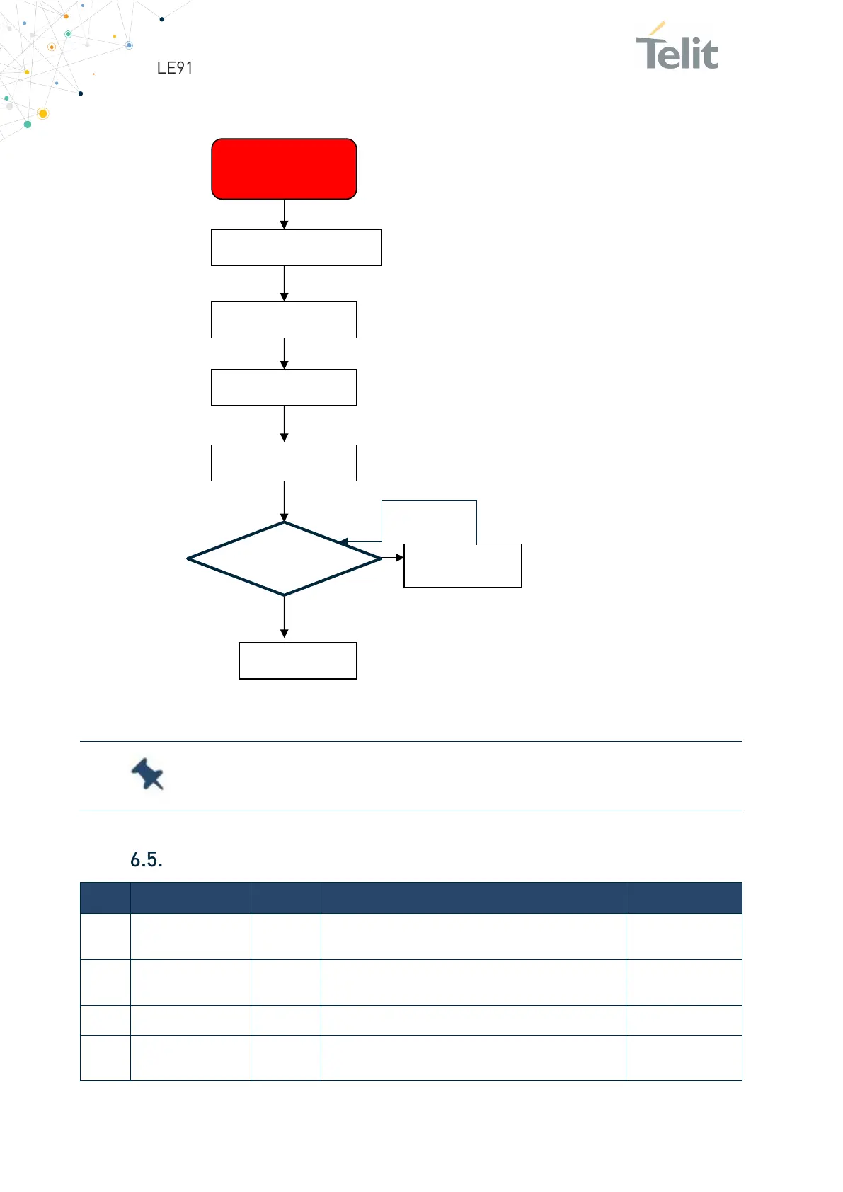
The below flow chart is detailed the proper power OFF procedure:
Figure 9: Power OFF Procedure
Control Signals
WAKE_N O
Active low signal used to wake up the system from
stand-by
3.3V
W_DISABLE_N I
Active low signal for wireless disabling (Airplane
3.3V
Active low functional reset to the card
LED_WWAN_N O
Active low, open drain signal for WWAN LED
driving, used to provide module’s status indication
3.3V
:
Software shutdown feature is not supported on early
engeeniring samples.
W_DISABLE_N = LOW
Delay 200ms
AT#SHDN
Delay 15s
Done
Delay 5s
 Loading...


