LE910Cx mPCIe Hardware Design Guide
1VV0301510 Rev. 13 Page 42 of 73 2021-07-07
6.6.2.1. Modem Serial Port 1 Signals
Serial Port 1 on LE910Cx-mPCIe is a +1.8V UART with 4 RS232 signals. It differs from the
PC-RS232 in signal polarity (RS232 is reversed) and levels.
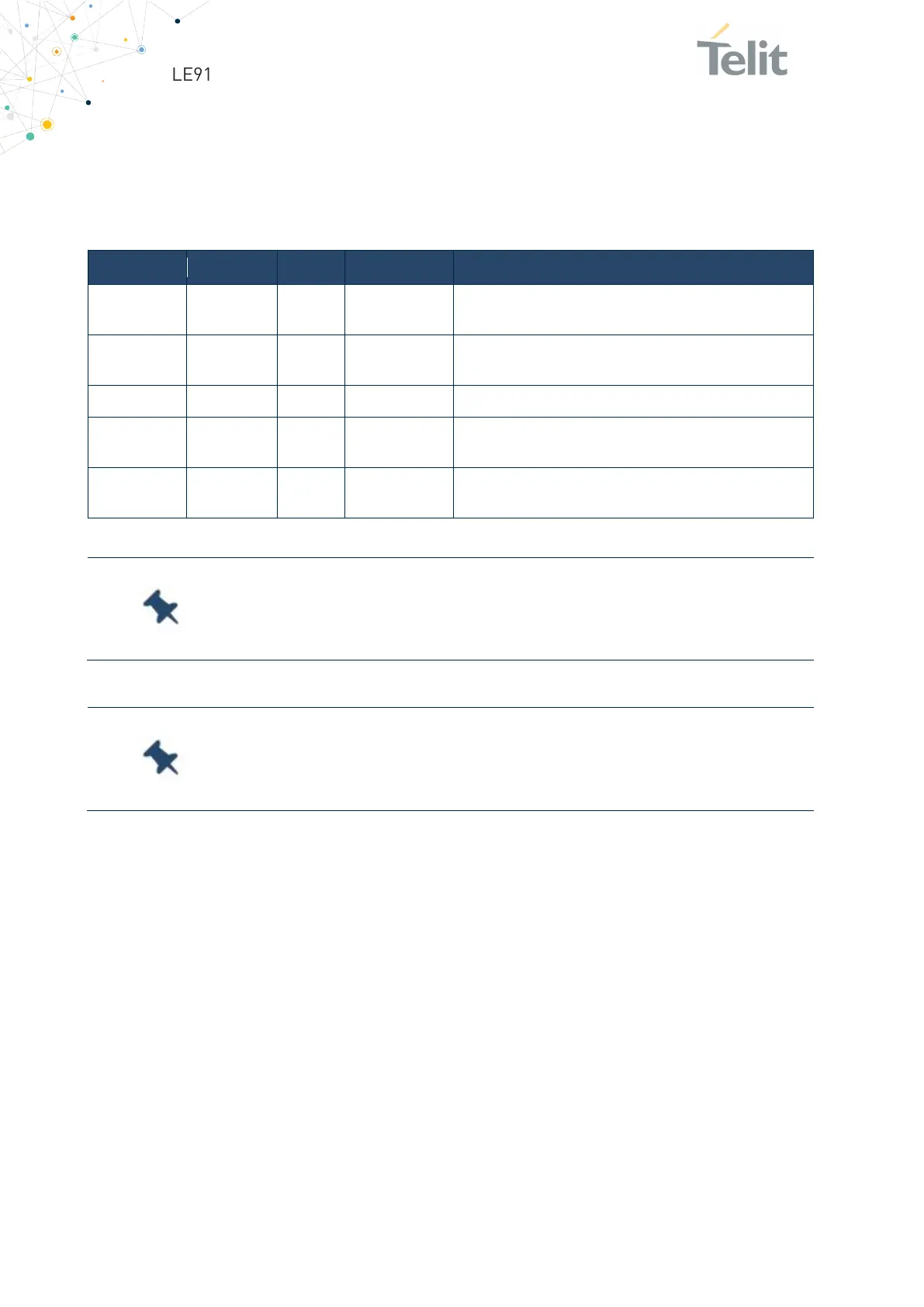
List of the signals of LE910Cx-mPCIe serial port:
RXD -
5 Transmit line Output transmit line of the LE910Cx-mPCIe UART
TXD -
3 Receive line Input receive line of the LE910Cx-mPCIe UART
RTS -
19
Request to
Input to LE910Cx-mPCIe controlling the Hardware flow
CTS -
17 Clear to Send
Output from LE910Cx-mPCIe controlling the Hardware
Table 20: LE910Cx-mPCIe Serial Port
To avoid a back-powering effect, it is recommended to prevent
any HIGH logic level signal from being applied to the digital pins of
the module when it is powered OFF or during an ON/OFF transition.
For minimum implementations, only the TXD and RXD lines
need be connected. The other lines can be left open provided a
software flow control is implemented.
6.6.2.2. RS232 Level Translation
To interface the LE910Cx-mPCIe with a PC com port or a RS232 (EIA/TIA-232) application,
a level translator is required. This level translator must:
• Invert the electrical signal in both directions
• Change the level from 0/1.8V to +15/-15V
The RS232 UART 16450, 16550, 16650 & 16750 chipsets accept signals with lower levels
on the RS232 side (EIA/TIA-562), allowing for a lower voltage-multiplying ratio on the
level translator. Note that the negative signal voltage must be less than 0V and therefore
some sort of level translation is always required.
 Loading...


