TL113046
Installation Manual Ford F650 TELMA AF50-90 SPL100 relay box 124 UIM
Page 5 of 18_____________________________________________________________________________15sep21jh
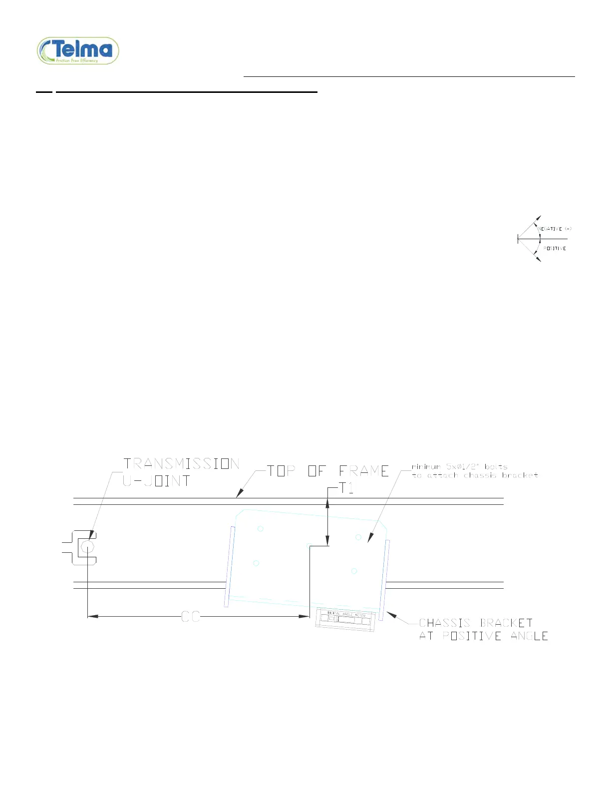
2.2 INSTALLATION OF THE CHASSIS BRACKETS
Remove any bolts such as battery box and/or exhaust hanger mounts that will interfere with the
chassis bracket mounting
Mark the reference hole at dimension T1 from the outside top of the frame down to the reference
hole and at dimension CC from the center of the transmission u-joint.
Drill a 5/8” hole in the frame and bolt the chassis bracket (TIB03104) against the outside of the
frame rail using the reference hole in the bracket.
Rotate the bracket to the angle specified on the installation drawing and tighten the reference bolt
and nut to 150 lb-ft (±10%) to hold the bracket in place at the correct angle.
Note: Use an electronic angle meter with 0.1° accuracy (e.g. Mitutoyo Pro 360 950-
317 digital protractor). Use “alt zero” to get a frame reference of zero degrees so
that all angles are measured with the frame at 0°. In order to maintain the frame
reference, do not rotate the angle meter in the horizontal plane after setting alternate
zero.
Drill four 1/2” holes in each chassis bracket and frame rail evenly distributed across the chassis
bracket using existing holes when possible. Keep away from fuel and brake lines and secure with
the 1/2”-20UNF x 1.75” flanged bolts (TIF05031) and 1/2”-20UNF flanged lock nuts (TIF05032)
included in the kit. Tighten to 100 lb-ft (±10%).
Drill through the chassis bracket any holes needed for battery box and/or exhaust hanger mounts
and reinstall the original bolts that were previously removed.
OUTSIDE VIEW DRIVER SIDE FRAME RAIL