This document outlines the maintenance procedures for replacing the hub on Telma AF8 series axial retarders, including LM/LN/LP/LR/LT models.
Function Description
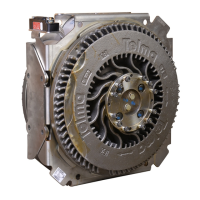
The Telma AF8 retarder is an emission-free braking system designed to provide supplementary braking for vehicles. It operates by generating an electromagnetic field that slows down the vehicle's drivetrain, reducing wear on the service brakes and enhancing safety. The core components include a stator, rotors, and a hub assembly, which are critical for its operation. The hub assembly connects the retarder to the vehicle's drivetrain, allowing the rotors to spin within the stator's magnetic field.
Important Technical Specifications
- Retarder Weight: A complete retarder weighs approximately 330 kg (728 lb).
- Rotor with Coupling Flange Weight: Approximately 63 kg (139 lb).
- Hub Weight: Approximately 5.5 kg (12 lb).
- Torque Values:
- Hub securing screws (pole shoe side): 45 Nm ± 20% (33 lb.ft ± 20%).
- Pole shoe securing screws: 68 Nm ± 20% (50 lb.ft ± 20%).
- Shaft end screws: 60 Nm ± 20% (44 lb.ft ± 20%).
- Axial Run Out (Stator): Maximum allowed value is 0.40 mm.
- Axial Run Out (Rotors): Maximum allowed value is 0.28 mm.
- Air Gap: Average of 10 values must conform to retarder technical specifications, typically 1.30 mm -0.20.
- Tab Washer Driver Dimensions:
- Ø A: 75 mm (2.953")
- Ø B: 24 mm +0.10 (0.945" / 0.949")
- C: 40 mm ± 0.1 (1.570" / 1.579")
- Material: XC 48F (Rm = 630 N/mm² mini) (HB 230 to 280).
- General machining: 6.3V except 3.2V.
- Protection: Oil burnishing.
- General tolerance: ± 0.5 mm (±.019 inch).
- Break sharp edges to have a 1 mm (.039 inch) chamfer at 45°.
Usage Features
The Telma AF8 retarder is designed for robust and reliable operation, providing supplementary braking without friction, thus extending the life of service brakes. Its design allows for relatively straightforward maintenance procedures, as detailed in the manual, to ensure continued optimal performance. The system's components are engineered for durability, but systematic replacement of certain parts during hub maintenance is crucial for maintaining its integrity and balancing.
Maintenance Features
The manual provides a comprehensive guide for hub replacement, emphasizing safety and precision.
- Systematic Part Replacement: During hub replacement, specific parts must be systematically replaced with new ones supplied with the spare hub assembly. These include shaft end screws, washers, air gap adjusting shims, lock tabs, screws for securing the hub, screws for securing the pole shoes plate, and dust protection washers.
- Required Tools: A specific set of tools is necessary, including protective glasses and gloves, handling safety tools, flat screwdriver, Torx® TX40 socket, click-type wrench, 10 mm and 19 mm long sockets, tab washer driver, hammer, feeler gauge, dial gauge with magnetic base, ink marker, torque wrench (with specified torque values), and abrasive cloth (120 grade).
- Dismantling Steps:
- Rotor Removal: Involves marking rotors and coupling flange for re-assembly orientation, removing lock tabs, unscrewing shaft end screws, and carefully removing dust shields and air gap adjusting shims.
- Stator Opening: Requires unscrewing hub securing screws on both gearbox and axle sides, positioning the stator horizontally on wooden blocks for shaft protection and hand access, and removing the pole shoes plate and pressure washers.
- Defective Hub Removal: Involves pulling out the hub assembly, taking care not to damage internal wiring or coil insulators. Cleaning core mating faces with abrasive cloth is also specified.
- Re-assembling Steps:
- New Hub Installation: Unpacking the new hub, lifting it into position, ensuring correct orientation for the vent cap, and carefully lowering it into the stator while minding coils and internal wiring.
- Coil and Washer Placement: Verifying that all output coils are correctly located in their notches and that pressure washers are properly placed on top of the coils.
- Pole Shoes Plate and Screw Installation: Relocating the pole shoes plate, ensuring spring washers are in place, and installing new screws for both the hub and pole shoes.
- Torque Application: Tightening screws in a specific order with a torque wrench to the specified values.
- Stator Flatness Check: Toggling the stator on wood blocks and checking axial run out with a dial gauge (max 0.40 mm).
- Rotor Installation: Lifting the stator vertically, placing new black shims and air gap adjusting shims, installing new dust shields, and re-installing rotors with coupling flange assemblies, ensuring alignment marks are matched.
- Shaft End Screw and Lock Tab Installation: Re-installing shaft end screws and pressure plates, applying specified torque, and inserting new lock tabs over screw heads with a hammer.
- Air Gap Adjustment: Measuring air gaps with a feeler gauge and adjusting shims if necessary to meet specifications (1.30 mm -0.20).
- Safety Precautions: The manual emphasizes reading it thoroughly before repair, ensuring operations are carried out by qualified personnel, and understanding and respecting all safety warnings, including those for potential damage to the retarder, surrounding equipment, and personal injury from heavy parts or electrical hazards.
- Genuine Spare Parts: The use of Telma genuine spare parts is highlighted, with references to specific spare parts catalogues (OC443068 for AF8 Telma Retarder) and air gap adjustment manuals (OC441xxx).
- Documentation: The document is the property of Telma and cannot be copied or forwarded without prior agreement, with any infringement leading to legal action.