This document is the property of Telma. It cannot be copied, forwarded, or given to any party without prior agreement form TELMA. Any infringement will immediately involve legal action.
TELMA S.A., 28 rue Paul Painlevé, F-95310 Saint-Ouen l’Aumône - www.telma.com 6 / 18 OC441691
6. DISMANTLING STEPS
A. REMOVAL OF ROTORS
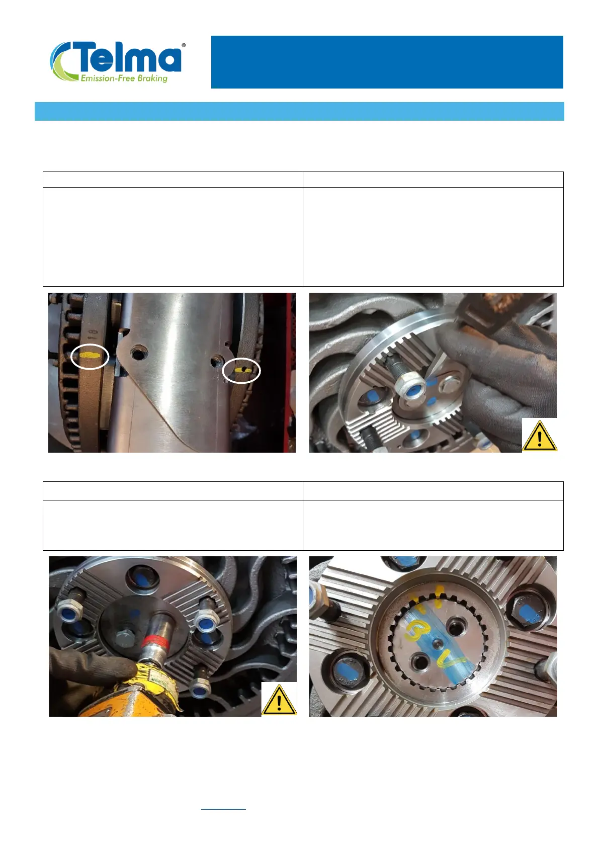
IMPORTANT: identify all parts before dismantling in order to find their initial orientations and
location during the re-assembly.
Draw a mark on each rotor outer edge with an ink
marker, the two marks must be aligned to find
again the initial angular orientation during re-
assembly. This is essential to maintain proper
balancing.
On the first retarder side (for instance here the
gearbox side, with the engraved part and serial
numbers), remove the lock tab by using a flat
screwdriver and a hammer. Caution: in order to
reduce the spring effect, suppress the stress in the
tab by hitting on one side and by removing the
other).
Unscrew the 2 shaft end screws to remove them.
Use a 19mm socket and a bar to lock the rotation
of the rotor.
Draw a mark on both shaft and coupling flange
with an ink marker, to find again the initial position.