TL113046
Installation Manual Ford F650 TELMA AF50-90 SPL100 relay box 124 UIM
Page 9 of 18_____________________________________________________________________________15sep21jh
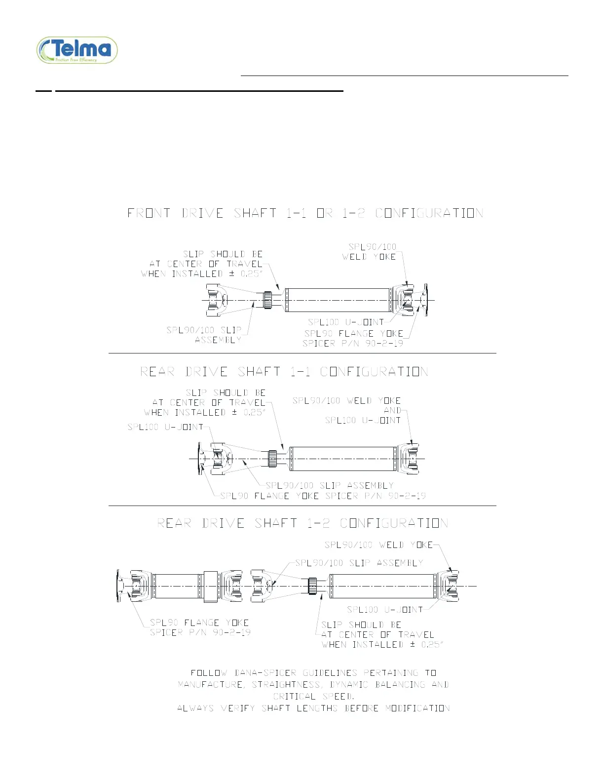
2.6 DRIVE SHAFT MODIFICATION AND INSTALLATION
A slip assembly is required on each side of the Telma. The slip position should be at center of slip travel when the shaft
is installed.
Refer to chassis manufacturers guidelines for proper drive shaft manufacture, balance, straightness, and critical speed
limits.
Refer to the installation drawings for approximate shaft lengths.
Always verify proper shaft lengths before modification.
Connect the flange yoke to the Telma coupling flange using 3/8-24UNF all metal locknuts TIF03001.