3
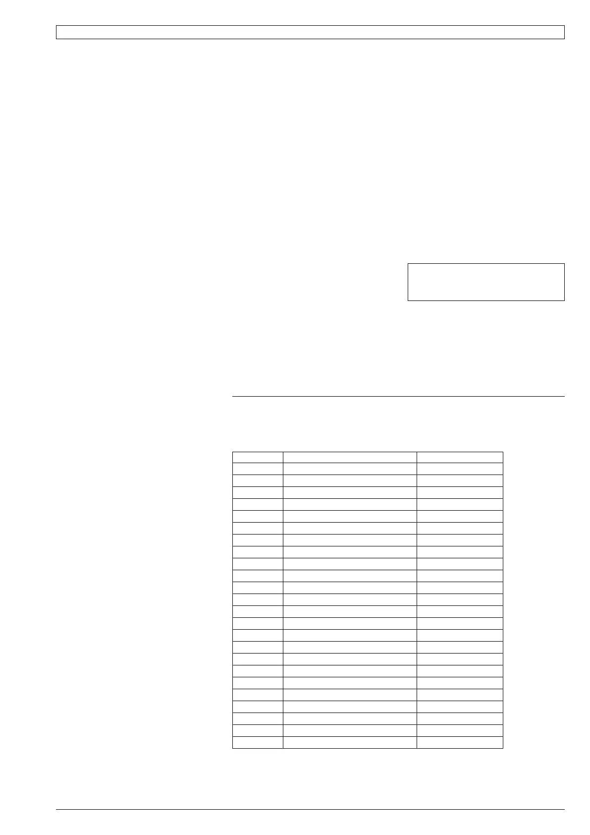
Table 1 SAT-2 Controller - Troubleshooting
If an fault is detected, an 'ERR' symbol will light up on the Wall plaque display.
The following error codes may be displayed:
Error Code Fault Remarks
1 Room sensor #1 failure Main board AD3
2 Room sensor #2 failure Main board AD4
3 Room sensor #3 failure Main board AD5
4 Room sensor #4 failure Main board AD6
5 #1 indoor coil sensor failure Main board AD1
6 #1 LST sensor failure Main board AD2
7 #1 insufficient refrigerant
8 #1 compressor overload
9 #1 low pressure failure
10 #1 high pressure failure
11 Room sensor #5 failure At wallpad B
12 Room sensor #6 failure At wallpad A
13 All room sensor failure
14 Float switch failure
15 #1 Low safety thermostat failure
16 Communication failure
17 Hydronic pump switch failure
18 #2 insufficient refrigerant
19 #2 compressor overload
20 #2 Low safety thermostat failure
21 Discharge sensor 1 failure
22 Discharge sensor 2 failure
23 Discharge temp 1 failure
24 Discharge temp 2 failure
Components
The following components are supplied in a
box taped inside the supply air spigot:
1. SAT-2 Wall Control plaque, including wall
mounting plate.
2. 10 m interface lead (electrical box-to-
plaque).
3. User's Operating Instructions booklet.
4. Lithium CR2032 battery (3V).
Optional
1. Remote return air sensor (in box).
2. Remote return air temperature sensor
lead; 1.5, 6, 12 or 25 m.
3. 20 m extended interface lead
(electrical box-to-plaque).
4. SAT-2 Zone Control PCB.
5. Zone Control 24V transformer.
6. Additional SAT-2 Wall Control plaque.
7. Infra red remote control.
Installation
The SAT-2 Controller PCB is supplied pre-
installed in the HWP unit's electrical box.
1. Isolate the HWP unit from power supply,
then remove electrical box cover.
2. Remove the SAT-2 box supplied taped
inside the supply air spigot.
3. Remove the Wall Control's interface lead
from this box and connect to the terminal
block (A1/B1/Vcc/GND) on the SAT-2
Controller board. Trace the remaining
length of the lead to the Wall Control's
intended location. Note: Make sure the
coloured wires are connected as per the
wiring diagram.
4. Remove the Wall Control's backing plate
by using a small screw driver to remove
the single screw at the bottom edge of
the plaque.
5. Install the Lithium battery, supplied loose,
positive (+) side up in the Wall Control's
battery holder.
6. Check the wall where the Wall Control
plaque is to be located is flat before
fastening the wall mounting plate.
Alternatively, the mounting plate can
be screwed to a standard wall socket
mounted horizontally.
Note: Use low profile (mush) headed
screws to prevent contact with the PCB
board. Fixing the plate to a distorted
surface may damage the control.
7. Drill hole in wall to allow cable entry.
8. Connect the interface lead to the the
Wall Control board. Note: Make sure
the coloured wires are consistently
connected at each end as per the wiring
diagram.
9. Ensure the interface lead is run
separately and away from main
power supply wires, including the
interconnecting cable. When installing
cabling, trim any excess length to suit
your location.
10. Fill around the interface lead with foam
or cover hole with PVC tape to prevent
draft from wall cavity affecting control
operation. Do not use aluminium duct tape.
11. Secure the Wall Control body to the
mounting plate by replacing the locking
screw removed earlier.
12.Replace the HWP electrical box cover.
Water Valve Control Option
Once the SAT-2 room thermosat reaches
the desired room temperature, it is capable
of switching off both the HWP unit's
compressor and an external water control
valve (if fitted); refer wiring diagram. This
provides economy of operation by reducing
the load on the central water supply system.
Remote Air Temperature Sensor/s
(option)
The air temperature sensor is by default
located in the Wall plaque. Optional remote
air temperature sensors are available
so that the measurement of the room
temperature can be taken away from the
wall plaque, eg. elsewhere in the room or in
the return air duct.
Remote sensor's can be plugged directly
into the Controller board (PCB). This
board accepts up to four sensors which
are designated as 'zones' one to four. The
first return air sensor will automatically
replace the Wall Control sensor and should
be located in the same room as the Wall
Control. The Controller will always use the
average of the zones selected. Refer to the
separate installation instructions supplied
with the PCB for further details.
Ensure all remote sensor wires are run
separately and away from main power
supply wires, including the interconnecting
cable.
Fault Detection
Any faults detected are displayed on the
SAT-2 Wall plaque (refer Table 1). A non-
specific fault output signal is also included
on SAT-2 Controllers for remote fault
indication to building management systems.
NOTE
The manufacturer reserves the right to
make changes in specifications at any time
without notice or obligation. Certified data is
available on request.
Units Supplied With Integrated Thermostat (SAT-2 Controller)
This pamphlet replaces the previous
issue no. 3669 dated 12/12.
CKSD & RKSD wiring rev.'s L & J resp.
 Loading...