GENERAL INSTALLATION
DUCTED WATER COOLED PACKAGED AIR CONDITIONERS
HWP models (c/w UC8)
Installation & Maintenance
1. GENERAL
1.1 Introduction
Follow these instructions to ensure the optimum
performance, reliability and durability.
Units must be installed in accordance with all national and
regional regulations and bylaws.
2. INSTALLATION
2.1 Positioning & Mounting
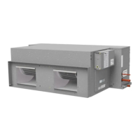
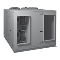
HWP units are designed to be used with simple, short
duct layouts. Units should be located as close to the
space to be air conditioned as acoustic criteria allows.
When determining the position of the air conditioner, allow
adequate space around the unit to facilitate water pipe/
hose connections, future servicing and maintenance.
Ensure there is enough working space in front of the
electrical access panel. Allow adequate clearance for the
lter to be withdrawn to its full length.
Mount the unit using the spring mount system supplied
(Fig.1). This system minimises transfer of vibration into
the building structure.
Figure 1 Spring Mounting
If a more rigid installation can
be tolerated, then suspend the
unit from four threaded rods
using locknuts (not supplied),
as shown in Fig. 2.
When nally positioned, tighten
the lock nuts on the mounting
rods to give a rm installation.
Alternatively, bolt the unit
directly to the ceiling's sub-
structure.
Figure 2 Solid Mounting
003-000-020 09/17
Tighten
locknuts
for strength
rod
Use 30x30
flat washers
supplied
Spring mount
support
supplied
National Health and Safety regulations must be followed
to avoid personal injuries.
The appropriate permits must be acquired and adhered
to.
Seismic restraints must be tted if required.
2.2 Condensate Drain & Optional Lift-Pump
Mount top of the unit level as it comes with a sloping
drain tray. This tray is reversible (ie the drain exit can
be at either end of the unit), unless tting the optional
Condensate Lift-Pump, in which case the exit must at the
opposite end to the compressor (ie standard orientation).
HWP 36–59: The condensate drain is NOT to be 'U'
trapped outside the unit.
HWP 78–275: The unit must be mounted with sufcient
height for the condensate drain to be 'U' trapped outside
the unit (see g.3). Alternatively t a condensate lift-pump.
The drain line must not be piped to a level above the drain
tray.
The drain line must be maintained at least 19 mm ID
along its full length. A vent pipe is recommended for
drain pipes longer than 4 m (refer gure 2). Check drain
by pouring water into the drain tray and ensuring that it
clears (with the unit operating). Failure to adhere to these
instructions could cause ooding.
OPEN
DRAIN
MINIMUM
SLOPE
20 mm PER m
(1 IN 50)
50 mm
MINIMUM
100 mm
APPROX.
'U' TRAP
100 mm
APPROX.
VENT PIPE
FOR LONG
CONDENSATE
DRAIN RUNS
UNIT
Figure 3 Condensate Drain
2.3 Air Ducts, Filters and Grilles
Rigid Ducting:
a. Use appropriately sized insulated ducting with
consideration for noise transmission through the
ducting. See recommendations at www.temperzone.
biz; model search 'application'.
b. Ensure rigid ducting is self-supported by its own
hangers and not by the unit.
d. If regular access to the unit is easy, the return air spigot
integrated lter can be used.
e. If the unit is inaccessible then install a return air grille
with lter incorporated in the ceiling instead.
f. Supply air grilles should be selected and installed to
avoid draughts and noise but give good air distribution.