1
Ducted Water Cooled R410A
Packaged Air Conditioner
HWP 35, 47, 58
Installation &
Maintenance
GENERAL
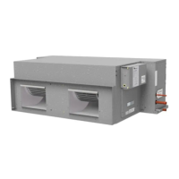
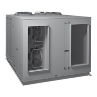
HWP - A general designation which
applies to all versions (refer fig.1)
These HWP units must be installed in
accordance with all national and local safety
codes.
OPTIONS
The following items are available as optional
extras:
1. Condensate Lift-Pump Kit.
2. Filter Box.
High pressure hoses (600 mm long) c/w
fitting and spring mounts are supplied as
standard.
AIR FILTRATION / FILTER BOX (Option)
As air filtration requirements vary, filters are
not supplied with the unit. Filters should
ideally be installed on the return air side of
the unit, no closer than 500 mm from the
back of the unit and easily accessible for
cleaning. To maximise the efficiency of air
flow, the return air filter should be twice the
area of the HWP unit's return air spigot/s. If
efficiency is less of a concern a Filter Box is
available.
The Filter Box is installed by unscrewing
the return air spigot and replacing it with the
Filter Box's filter-integrated spigot. The filter
may be accessed from either side of this
spigot. This box adds 90 mm to the overall
depth of the unit.
INSTALLATION
Positioning & Mounting
HWP units are designed to be used with
simple, short duct layouts. Units should
be located as close to the space to be air
conditioned as acoustic criteria allows; refer
to Fig. 6 for application considerations.
When determining the position of the air
conditioner, allow adequate space around
the unit to facilitate future servicing and
maintenance. Ensure there is enough
working space in front of the electrical
access panel. Allow adequate clearance for
the filter (optional) to be withdrawn to its full
length.
It is recommended that the unit be
mounted using the spring mount system
supplied (Fig.3). This system minimises
transfer of vibration into the building
structure.
If a more rigid installation can be tolerated,
then suspend the unit from four threaded
rods using locknuts (not supplied), as shown
in Fig. 4.
E
HANGING CENTRES
20 X 9 SLOTS
A
OVERALL
ACCESS
PANEL
DRAIN 19 OD
WATER CONN'S:
TWO BSP MALE
13 mm (1/2")
ELECTRICAL
BOX
ELECTRICAL
CONDUIT HOLES
B
SUPPLY AIR SPIGOT
257
440
HANGING
CENTRES
SLOPING
DRAIN TRAY
355
OVERALL
472
OPTIONAL
SPRING MTG
CENTRES
F
OPTIONAL
SPRING MOUNTING CENTRES
C
55
75
D
COIL
150
OPTIONAL
R/A FILTER BOX WITH
FILTER ACCESS
EACH SIDE
OPTIONAL
FILTER BOX
G
(HEIGHT = 257)
IN
OUT
(WATER)
55
685
OVERALL
40
Fig. 2 Dimensions (mm)
Not to Scale
MODEL A B C D E F G
HWP 35 845 477 40 105 825 900 480
HWP 47 845 477 40 105 825 900 480
HWP 58 1110 742 45 90 1090 1165 745
Net Weight
HWP 35 57 kg
HWP 47 58 kg
HWP 58 75 kg
C - Cooling only
CE - Cooling only with electric heat
R - Reverse cycle
K - Refrigerant R410A
S - Single phase power supply
T - Three phase power supply
D - Integrated Thermostat
N - Protection board
H
H - Hideaway
W - Water Sourced
P - Packaged
Divide by 10
to get approx.
nominal
Capacity in
kilowatts
Series Size Type
CW P 3 5 K
e.g.
S D
Fig. 1 Nomenclature