WATER CONNECTIONWIRING
- 2 -
3 WATER CONNECTION
3.1 General
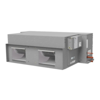
The HWP unit's IN and OUT water connections are male
BSP pipe threaded. The unit can be piped directly or
using two temperzone exible high pressure water hoses
(supplied) which have female pipe threaded connections
at each end.
Poor quality water supply must be pre-ltered and it is
essential that adequate water treatment is maintained,
particularly where open cooling towers are used.
Note: It is recommended that the water supply system be
tted with a water ow switch and water ow verication
circuit. These items prevent the HWP units from going
into fail safe lockout status due to a loss of water ow.
Failure to install the above items could require the
resetting of all HWP units in the system – by breaking the
power supply to each unit or by Modbus command.
3.2 Circuit Balancing Valve
It is recommended that a circuit balancing valve be tted
to maintain water ow at a constant rate. The minimum
water ow rates in litres per second (l/s) are stated in the
supplied Specications Data sheet.
The HWP unit controller will protect the refrigeration
system of the unit under severe operating conditions.
On heating cycle it protects to ensure the evaporating
temperature does not drop below freezing for an
extended period. The extreme lowest leaving water
temperature needs to be such that the unit does not
cut-out on protection and will be above approx. 4°C. This
can be achieved by a combination of the Entering Water
Temperature (EWT) and the reduced ow rate. Water
ow needs to be balanced to suit the system design.
Refer Technical Data for accepatble water ow rates and
pressure drop data.
4. WIRING
4.1 General
Electrical power wiring must be tted and certied by
persons with appropriate qualications and certication.
A signed 'Certicate of Compliance' must be left with the
unit for insurance purposes.
4.2 Power to Unit
All power wiring is to be done to the appropriate electrical
standard of the country in which the unit is being installed.
The person installing the wiring is responsible for the
correct selection of wiring size and auxiliary components.
See the Specication Sheet for supply voltage range,
frequency, phase and maximum operating current .
Wire the unit directly from the Electrical Distribution Board.
The unit should have its own dedicated circuit breaker
on the Distribution Board and an isolator switch should
be installed in accordance with the applicable wiring
regulations.
4.3 Control
Room Temperature Controller
(Reverse Cycle Models)
The thermostat should be set within the recommended
operating range of between 19°C and 30°C.
Various options are available to control the air
conditioning unit operation.
a. Temperzone TZT-100 Wall Thermostat.
Refer to www.temperzone.biz for features and
installation details; model search 'TZT-100'.
Separate 'Installer' and 'User' instructions are
supplied with the TZT-100 for installation and
operation.
b. The Temperzone SAT-3 Wall Thermostat.
Refer to www.temperzone.biz for features and
installation details; model search 'SAT-3'.
Separate instruction booklets come with the SAT-3
for installation and operation.
Remote temperature sensors are available
separately and can be installed to enhance the
systems functionality.
Note: Ensure the remote sensor wires are run
separately and away from main power supply wires,
including the interconnecting cable.
3.3 Air / Water Flow
Refer to HWP Technical Data pamphlets at
www.temperzone.biz for detailed information on air
handling performance and water ow rates.
3.4 Water Circulating Pump & Flow Verication Option
In order to promote efciency and avoid running the
water circulation pump unnecessarily, the unit's UC8
Controller can be used to control the activation of the
pump prior to running the compressor. After activation
of the external water circulating pump, the UC8 waits for
the ow verication contact to close before energising
the compressor contactor and therefore starting the
compressor (refer wiring diagram, p.7). The UC8 also
de-activates the pump when the compressor stops.
3.5 Water Regulating Valve Control Option
A 0-10V signal is available on output V1 for the control
of a water ow control valve (optional; not supplied by
temperzone); refer wiring diagram. When used, the valve
is closed (0V signal) when the compressor is off. When
the unit is cooling the signal will control the valve to obtain
an optimum condensing temperature. When the unit is
heating (reverse cycle units) the valve is directed fully
open (10V signal).
3.6 Water Shut-Off Valve Option
This will ensure the water is not owing through the
unit when it is not operational for a long period of time,
thereby reducing the overall central pump power usage.
The water shut-off relay on the HWP can be used to
activate a water shut-off valve (supplied and tted by
others).
 Loading...