INSTALLATION INSTRUCTIONS Gas Furnace: (F/G)MAC
28 440 01 4201 01
Specifications subject to change without notice.
The J−Box cover, mounting bracket and screws are shipped in
the loose parts bag included with the furnace. The J−Box can
be mounted on the left or right side of the casing, as viewed
from the upflow position. (See Figure 35)
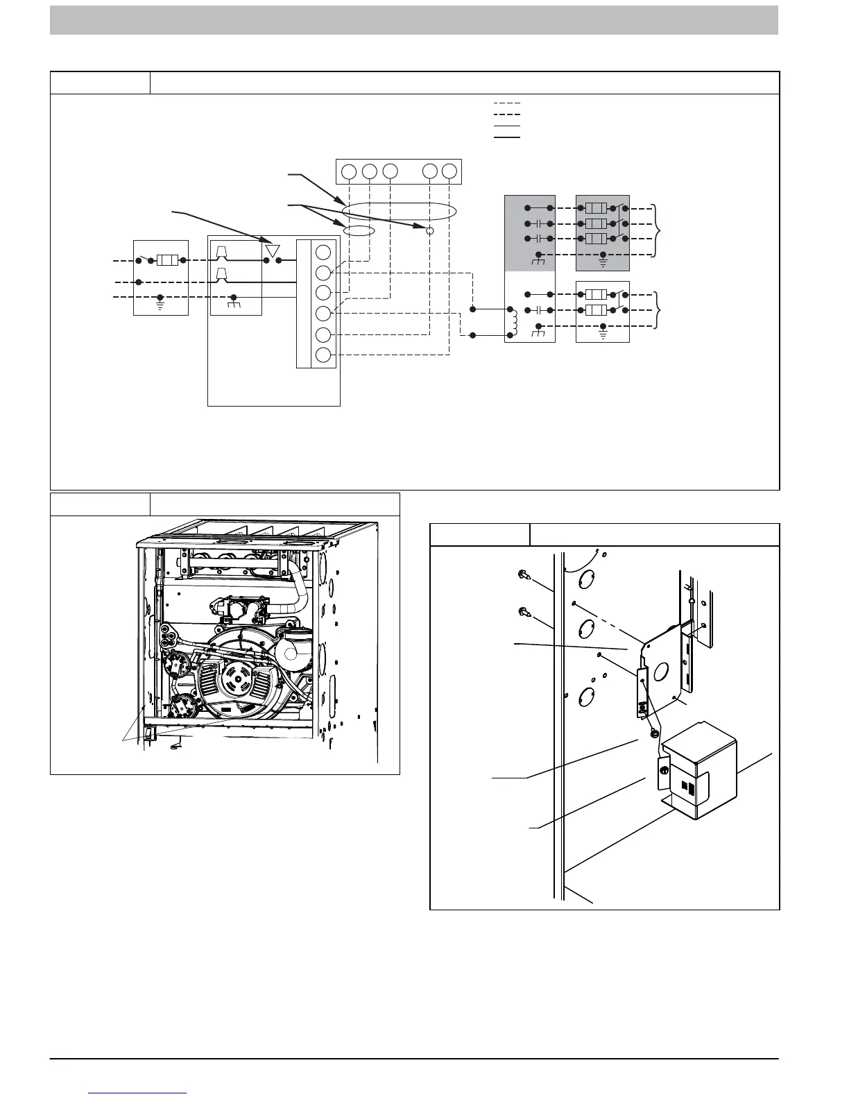
Figure 34 Typical 2−Stage Field Wiring Diagram
A11401
115-VOLT FIELD-
SUPPLIED
FUSED
DISCONNECT
JUNCTION
BOX
24-VOLT
TERMINAL
BLOCK
THREE-WIRE
HEATING-
ONLY
FIVE
WIRE
NOTE 2
NOTE 1
1-STAGE
THERMOSTAT
TERMINALS
FIELD-SUPPLIED
FUSED DISCONNECT
CONDENSING
UNIT
FURNACE
COM
R
WC Y RG
GND
GND
FIELD 24-VOLT WIRING
FIELD 115-, 208/230-, 460-VOLT WIRING
FACTORY 24-VOLT WIRING
FACTORY 115-VOLT WIRING
Connect Y/Y2-terminal as shown for proper operation.
Some thermostats require a "C" terminal connection as shown.
If any of the original wire, as supplied, must be replaced, use
same type or equivalent wire.
208/230- OR
460-VOLT
THREE
PHASE
208/230-
VOLT
SINGLE
PHASE
WHT
BLK
WHT
BLK
W/W1
W2
Y/Y2
G
NOTES: 1.
2.
3.
BLOWER
DOOR
SWITCH
C
O
N
T
R
O
L
Figure 35 J−Box Location
J BOX LOCATIONS
Representative drawing only, some models may vary in appearance.
Remove the J−Box cover and mounting bracket from the loose
parts bag. Select a 7/8−in. (22 mm) knock-out on the desired
side of the casing. Remove the knock-out from the casing. Drill
two 1/8−in. (3 mm) pilot holes in the casing dimples by the
desired 7/8−in. (22 mm) knock-out.
Align the J−Box mounting bracket against the inside of the
casing and secure the mounting bracket with the screws. (See
Figure 36)
Electrical Box on Furnace Casing Side
NOTE: Check that duct on side of furnace will not interfere with
installed electrical box.
1. Fasten a field-supplied external electrical box to the
outside of the casing by driving two field-supplied
screws from inside electrical box into casing. (See
Figure 37)
2. Route field power wiring into external electrical box.
3. Pull furnace power wires through 1/2-in. (12 mm)
diameter hole in J−Box. If necessary, loosen power
wires from strain−relief wire-tie on furnace wiring
harness.
4. Connect any code required external disconnect(s) to
field power wiring.
Figure 36 J−Box Bracket Installation
A11F003
J−BOX
MOUNTING
SCREWS
J−BOX
MOUNTING
BRACKET
GROUND
SCREW
J−BOX COVER
5. Route external field power wires through holes in
electrical box and casing.
6. Connect field ground wire and factory ground wire to
green ground screw on J−Box mounting bracket as
shown in Figure 36.
7. Connect field power and neutral leads to furnace power
leads. as shown in Figure 34.