INSTALLATION INSTRUCTIONS Gas Furnace: (F/G)MAC
440 01 4201 01 29
Specifications subject to change without notice.
8. Attach furnace J−Box cover to mounting bracket with
screws supplied in loose parts bag. Do not pinch wires
between cover and bracket.
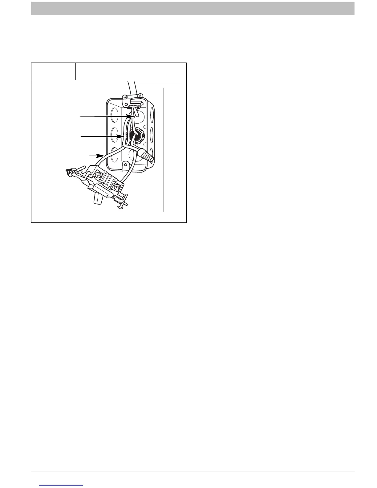
9. Complete external disconnect wiring and installation.
Connect line voltage leads as shown in Figure 37. Use
best practices (NEC in U.S. for wire bushings, strain
relief, etc., and Canadian Electrical Code CSA C22.1.)
Figure 37
Field−Supplied Electrical Box on
Furnace Casing
A10141
GROUND
NEUTRAL
LINE VOLTAGE
Power Cord Installation in Furnace J−Box
NOTE: Power cords must be able to handle the electrical
requirements listed in Table 9. Refer to power cord
manufacturer’s listings.
1. Install J−Box mounting bracket to inside of furnace
casing. (See Figure 36)
2. Route listed power cord through 7/8−in. (22 mm)
diameter hole in casing and J−Box bracket.
3. Secure power cord to J−Box bracket with a strain relief
bushing or a connector approved for the type of cord
used.
4. Pull furnace power wires through 1/2−in. (12 mm)
diameter hole in J−Box. If necessary, loosen power wires
from strain—relief wire−tie on furnace wiring harness.
5. Connect field ground wire and factory ground wire to
green ground screw on J−Box mounting bracket as
shown in Figure 36.
6. Connect power cord power and neutral leads to furnace
power leads as shown in Figure 34.
7. Attach furnace J−Box cover to mounting bracket with
screws supplied in loose parts bag. Do not pinch wires
between cover and bracket.
BX Cable Installation in Furnace J−Box
1. Install J−Box mounting bracket to inside of furnace
casing.
2. Route BX connector through 7/8−in. (22 mm) diameter
hole in casing and J−Box bracket.
3. Secure BX cable to J−Box bracket with connectors
approved for the type of cable used.
4. Connect field ground wire and factory ground wire to
green ground screw on J−Box mounting bracket as
shown in Figure 36.
5. Connect field power and neutral leads to furnace power
leads. as shown in Figure 34.
6. Attach furnace J−Box cover to mounting bracket with
screws supplied in loose parts bag. Do not pinch wires
between cover and bracket.
24−V Wiring
Make field 24−v connections at the 24−v terminal strip. (See
Figure 39) Connect terminal Y/Y2 as shown in Figure 34 for
proper cooling operation. Use only AWG No. 18, color−coded,
copper thermostat wire.
NOTE: Use AWG No. 18 color-coded copper thermostat wire
for lengths up to 100 ft. (30.5 M). For wire lengths over 100 ft.,
use AWG No. 16 wire.
The 24−v circuit contains an automotive−type, 3−amp. fuse
located on the control. Any direct shorts during installation,
service, or maintenance could cause this fuse to blow. If fuse
replacement is required, use ONLY a 3−amp. fuse of identical
size.
Thermostats and Control Settings
For best results, use a communicating wall control to control
this modulating furnace. A single stage or two−stage heating
and cooling thermostat can be used with the furnace. The
furnace control board CPU will control the furnace and outdoor
unit staging. A two stage heating and cooling thermostat can
also be used to control the staging. However, full modulating
capability will not be available when the furnace staging is
controlled by the thermostat. Furnace staging will be limited to
Minimum and Maximum inputs or Intermediate and Maximum
inputs depending on the configuration of set-up switches
SW1-2 and SW4-2. Refer to typical thermostat wiring diagrams
and the Sequence of Operation section for additional details.
Consult the thermostat installation instructions for specific
information about configuring the thermostat.
Accessories (See Figure 38 and Figure 39)
1. Electronic Air Cleaner (EAC)
Connect an accessory Electronic Air Cleaner (if used)
using 1/4−in female quick connect terminals to the two
male 1/4−in quick−connect terminals on the control
board marked EAC−1 and EAC−2. The terminals are
rated for 115VAC, 1.0 amps maximum and are
energized during blower motor operation.
2. Humidifier (HUM)
The HUM terminal is a 24 VAC output, energized
when the blower is operating during a call for heat.
Connect an accessory 24 VAC, 0.5 amp. Maximum (if
used) to the 1/4−in male quick−connect HUM terminal
and COM−24V screw terminal on the control board
thermostat strip.
NOTE: If the humidifier has its own 24 VAC power supply, an
isolation relay may be required. Connect the 24 VAC coil of the
isolation relay to the HUM and COM/24V screw terminal on the
control board thermostat strip.
3. Communication Connector
This connection is used when the furnace is
controlled by an optional communicating wall control
instead of a standard thermostat. The communication
plug is supplied with the communicating wall control.
Refer to the instructions supplied with the
communicating wall control for complete details.
4. Outside Air Thermistor (OAT)
The OAT connection is used in conjunction with
communicating wall control. It is not required when the
furnace is controlled by a standard type thermostat.