31
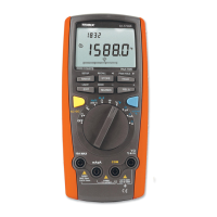
To measure voltage, set up the Meter as Figure 3-1
and do the following:
Insert the red test lead into the V terminal and the
black test lead into the COM terminal.
Set the rotary switch to or or
Connect the test leads across the object being
measured.
The measured value shows on the display.
AC measurement displays the True RMS value.
DC measurement displays the effective value of sine
wave (mean value response).
1.
2.
3.
4.
When a ACV function is selected, you can press the
Yellow Button to view the AC + DC True RMS value
in the primary display. To exit, please EXIT button.
The BLUE button cycles among , frequency and
duty cycle.
mV
V
mV
V
V
V
Note
When measuring voltage, the Meter acts around a
10M
( and ) or 2.5G ( ) impedance in
parallel with the circuit. This loading effect can cause
measurement errors in high impedance circuits. In
most cases, the error is negligible (0.1 or less) if
the circuit impedance is 10k
or less.
Special care should be taken when measuring high
voltage.
When voltage measurement has been completed,
disconnect the test leads from the circuit under test
and remove the test leads from the input terminals
of the Meter.
l
l
l
mV
Model 72-7730A/72-7732A: OPERATING MANUAL
 Loading...