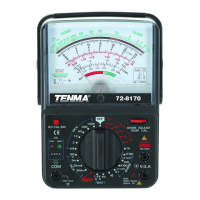
The Tenma Model 72-8170 is an analog Volt/Ohm Meter designed for various electrical measurements. It is a portable device suitable for testing and troubleshooting in a range of applications.
Function Description
The device primarily functions as an analog multimeter, capable of measuring:
- DC Voltage (DCV): Measures direct current voltage.
- AC Voltage (ACV): Measures alternating current voltage.
- DC Current (DCA): Measures direct current.
- Resistance (Ohms): Measures electrical resistance.
- Continuity: Checks for a continuous electrical path, indicated by an audible beep.
- Battery Test: Assesses the condition of 1.5V and 9V batteries.
- Transistor Type Check: Identifies whether a transistor is PNP or NPN.
- Decibel (dB) Measurement: Measures decibel levels in AC voltage ranges.
The meter features a large analog display with an indicator pointer for readings and a range selector for choosing the desired measurement type and range. It also includes input terminals for test leads, a 10A input terminal for high current measurements, and transistor input terminals for testing. A zero calibration adjustment and a calibration pushbutton are provided for accurate readings, especially for resistance measurements. The device is equipped with a carry handle/stand for convenience.
Important Technical Specifications
DC Voltage (DCV):
- Ranges: 0.6V, 3.0V, 12V, 60V, 300V, 1000V
- Accuracy: ±3% full scale (for 0.6V to 300V), ±5% full scale (for 1000V)
- Input Impedance: 20KΩ/volt
AC Voltage (ACV):
- Ranges: 12V, 30V, 120V, 300V, 1000V
- Accuracy: ±4% full scale (for 12V to 300V), ±5% full scale (for 1000V)
- Input Impedance: 9KΩ/volt
DC Current (DCA):
- Ranges: 120μA, 3mA, 30mA, 300mA, 10A
- Accuracy: ±3% full scale (for 120μA to 300mA), ±5% full scale (for 10A)
Ohms:
- Ranges: x1Ω, x10Ω, x1KΩ, x10KΩ
- Accuracy: ±3% of arc
Continuity:
Battery Test:
- 1.5V: @ 300mA
- 9V: @ 30mA
- Displays: Replace/Good
General Specifications:
- Operating Temperature Range: 0~40° C
- Relative Humidity: ≤80%
- Power Source: 2x 1.5V AA batteries, 1x 9V battery
- Fuse: 0.5A fast blow, 5 × 20mm
- Dimensions: 6.7" (H) x 4.9" (W) x 1.9" (D)
- Included Accessories: Test leads, instruction manual
Usage Features
General Tips:
- Always read the manual thoroughly before use and keep it for future reference.
- Ensure test leads are correctly connected: red to (+) input terminal, black to (-) input terminal, and fully inserted into sockets.
- When measuring resistance, perform zero adjustment after each range change.
- Set the meter to the OFF position when not in use to protect the meter movement.
- When measuring unknown voltages, start at the highest range and work downwards.
DC Voltage Measurement:
- Set the range selector to the appropriate DCV position.
- Connect the red lead to the (+) VΩA input and the black lead to the (-) COM input.
- Connect test leads in parallel to the load, observing correct polarity.
- Read the value on the DC scale, ensuring the correct scale for the selected range is used.
AC Voltage Measurement:
- Set the range selector to the appropriate ACV position.
- Connect the red lead to the (+) VΩA input and the black lead to the (-) COM input.
- Connect test leads in parallel to the load.
- Read the value on the AC scale, ensuring the correct scale for the selected range is used.
DC Current Measurement (≤300mA):
- Set the range selector to the appropriate DCA position.
- Connect the red lead to the (+) VΩA input and the black lead to the (-) COM input.
- Connect test leads in series to the load (the meter must be part of the circuit).
- Read the value on the DC scale, ensuring the correct scale for the selected range is used.
DC Current Measurement (>300mA):
- Set the range selector to the DC 10A position.
- Connect the red lead to the DC10A 10A MAX input and the black lead to the (-) COM input.
- Connect test leads in series to the load (the meter must be part of the circuit).
- Read the value on the topmost DC scale. Note that "10" on this scale represents full 10A measurement.
- Important Note: Measurements exceeding 5A should not be performed for more than 20 seconds.
Testing Continuity:
- Set the range selector to the .))) position (one position counterclockwise from the x1 OHMS scale).
- Connect the red lead to the (+) VΩA input and the black lead to the (-) COM input.
- Connect test probes to the circuit or device.
- The internal buzzer will sound if continuity exists (circuit impedance below 100Ω).
Resistance Measurement (Ω):
- Important Note: Ensure no voltage is present in the circuit, and any capacitors are discharged, as even small voltages can damage the meter in OHMS range.
- Set the range selector to the appropriate Ω position.
- "Zero" the meter by simultaneously depressing the 0Ω CAL. SW button and rotating the OHMS ADJUST control until the meter displays "0" ohms. If zero cannot be obtained, replace batteries.
- Connect the red lead to the (+) VΩA input and the black lead to the (-) COM input.
- Connect test probes to the circuit or device. Avoid touching metal probe tips with fingers, as body resistance will affect readings.
- Read the value on the OHM scale and multiply it by the range multiplier.
- For best accuracy, select a range that provides a reading closest to the center of the scale.
- Perform the Zero meter function each time the OHMS scale is changed for accurate readings.
Decibel (dB) Measurement:
- Set the range selector to one of the ACV ranges.
- Connect the red lead to the (+) VΩA input and the black lead to the (-) COM input.
- When using the 12V range, read the measurement directly from the dB scale.
- For other scales, add the appropriate dB value from the provided table (e.g., 8 dB for 30V, 20 dB for 120V, 28 dB for 300V, 40 dB for 1000V).
Battery Test:
- Connect the red lead to the (+) VΩA input and the black lead to the (-) COM input.
- Select the proper range: 1.5V for "AAA", "AA", "C", "D" type batteries; 9V for rectangular 9V batteries.
- Connect the black lead to the negative terminal and the red lead to the positive terminal of the battery.
- The BAT scale will indicate GOOD, REPLACE, or Questionable status.
- Note that this provides relative battery condition. Reference loads: 9V, 30mA; 1.5V, 300mA.
Transistor Type Check:
- Insert the transistor into the correct socket inputs labeled Emitter, Base, and Collector.
- Select the TR position on the Range Selector.
- The red LED indicates a PNP transistor, and the green LED indicates NPN.
Maintenance Features
Cleaning and General Maintenance:
- Periodically wipe the case with a damp cloth and mild detergent. Avoid abrasives or solvents.
- Clean terminals and test probes with standard spray contact cleaner to prevent dirt and moisture from affecting readings.
- Turn the meter to the OFF position when not in use.
- Remove batteries if the meter will not be used for a long period.
- Do not attempt to repair or service the meter unless qualified.
- Avoid electrical shock or damage by preventing water from entering the case.
- Do not store the meter in high humidity or temperature.
Battery Replacement:
- Replace batteries if the meter cannot be calibrated to zero on the OHMS scale.
- Ensure test leads are removed from the circuit and disconnected from the meter.
- Remove the three Philips head screws from the rear of the meter housing.
- Remove the rear housing from the meter assembly.
- Locate and replace the three batteries (2x AA, 1x 9V).
- Only good quality alkaline batteries are recommended.
- Replace the rear housing and reinstall the screws.
Replacing the Fuse:
- Ensure test leads are removed from the circuit and disconnected from the meter.
- Remove the three Philips head screws from the rear of the meter housing.
- Remove the rear housing from the meter assembly.
- Locate and replace the fuse in its socket on the internal PC board.
- Replace with only a comparable 5mm x 20mm 0.5A 250V fast blow type fuse.
- Replace the rear housing and reinstall the screws.
- Important Note: Fuse replacement is rarely needed; a blown fuse usually indicates improper meter use.