Tips for Use
• This manual should be read thoroughly before use and kept for future reference.
• Make certain that the red lead is connected to the (+) input terminal, and the black lead
is connected to the (–) input terminal.
• Make certain the leads are fully inserted into the meter input sockets.
• When measuring resistance, check the zero adjustment after each change of
measurement range.
• Set the meter to the OFF position when not in use. This will engage dampening,
providing protection to the meter movement.
• When measuring voltage, if the approximate voltage is unknown, start at the top range
and work down.
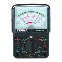
DC Voltage Measurement
• Set the range selector to the proper DCV position.
• Connect the red lead to the (+) VA input.
• Connect the black lead to the (–) COM input.
• Keeping certain to observe correct polarity, connect the test leads in parallel to the
load to be measured.
• Read the value on the DC scale, be sure to use the correct scale for the range
selected.
AC Voltage Measurement
• Set the range selector to the proper ACV position.
• Connect the red lead to the (+) VA input.
• Connect the black lead to the (–) COM input.
• Connect the test leads in parallel to the load to be measured.
• Read the value on the AC scale, be sure to use the correct scale for the range
selected
DC Current Measurement (300mA)
• Set the range selector to the proper DCA position.
• Connect the red lead to the (+) VA input.
• Connect the black lead to the (–) COM input.
• Connect the test leads in series to the load to be measured. In other words, the meter
must be part of the circuit to be measured.
• Read the value on the DC scale, be sure to use the correct scale for the range
selected
DC Current Measurement (>300mA)
• Set the range selector to the DC 10A position.
• Connect the red lead to the DC10A 10A MAX input.
• Connect the black lead to the (–) COM input.
• Connect the test leads in series to the load to be measured. In other words, the meter